CY545 Stepper System Controller
www.ControlChips.com
CY545 DIP & CY545/J PLCC Pin Descriptions
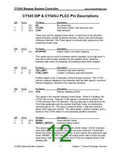
DIP
PLCC
Pin Name
Description
-
1
2
1
2
3
(O)
(O)
NC
No connection
Step pulse output, one pulse per step
Step direction
PULSE/
(I/O) CCW
These pins run the stepper power driver. A high level on the direction
signal indicates counter clockwise direction, while a low level indicates
clockwise direction. The Pulse signal is normally high, going low at the
beginning of each step.
DIP
3
PLCC
4
Pin Name
STOPPED
Description
Motion status, low while stepping
(O)
This signal may be used to indicate motion complete, by its high level. It
may also control power selection for the stepper driver, switching
between high power for stepping, and parking power while stopped.
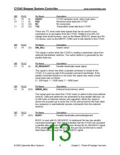
DIP
PLCC
Pin Name
Description
4
5
5
6
(I)
(I)
CW_LIMIT/
CCW_LIMIT/
Clockwise step limit reached
Counter Clockwise step limit reached
If either signal is low, it indicates a limit has been reached. The CY545
will not continue stepping in that direction until the limit signal is removed.
Normal stepping is allowed in the opposite direction.
DIP
6
PLCC
7
Pin Name
(I/O) JOG
Description
Manual stepping control
This signal is the manual stepping control input. When it is floating, the
CY545 will not jog. However, if the signal is connected to ground, the
CY545 will jog in the CW direction. The jog step rate is derived from the
First Rate parameter and the normal Step Rate Table, by dividing the
selected rate by 20. This gives a range of about 1 step per second to
about 1000 steps per second. The input signal is always enabled, and is
tested by the CY545 while it is not executing another command.
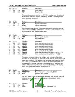
DIP
PLCC
Pin Name
Description
7
8
8
9
(I/O) SLEW/
Slew indicator signal
External motion control
(I)
INHIBIT_ABORT/
This signal group indicates and controls motion status. SLEW/ indicates
when the maximum selected step rate has been achieved. If externally
driven low at the beginning of a motion, it also selects the continuous step
mode. INHIBIT_ABORT/ can hold off motion at the start or force an early
down ramp, then stop motion when the CY545 has ramped down to the
starting rate.
© 2002 Cybernetic Micro Systems
7
Chapter 2 - Pinout & Package Overview

 ETC [ ETC ]