MITSUBISHI MICROCOMPUTERS
7470/7471 Group
SINGLE-CHIP 8-BIT CMOS MICROCOMPUTER
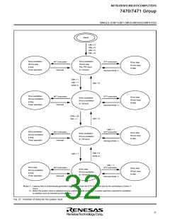
Reset
CM
4
5
6
7
= 0
= 0
= 0
= 0
CM
CM
CM
f(XIN) oscillation
f(XCIN) stop
φ stop
f(XIN) oscillation
f(XCIN) stop
WIT instruction
Interrupt
STP instruction
f(XIN) stop
f(XCIN) stop
P5
0, P51 input
φ stop
Timer operation
φ = f(XIN)/2
Interrupt (Note 1)
CM
5
4
= 1
= 1
CM
CM
4
= 0
(Note 2)
f(XIN) oscillation
f(XCIN) oscillation
φ stop
WIT instruction
Interrupt
STP instruction
f(XIN) stop
f(XIN) oscillation
f(XCIN) oscillation
φ = f(XIN)/2
f(XCIN) stop
φ stop
Timer operation
Interrupt (Note 1)
(CM
CM
5
= 0)
CM7 = 0
7
= 1
CM5 = 1
f(XIN) oscillation
f(XCIN) oscillation
φ stop
WIT instruction
Interrupt
STP instruction
f(XIN) stop
f(XIN) oscillation
f(XCIN) oscillation
φ = f(XCIN)/2
f(XCIN) stop
φ stop
Timer operation
Interrupt (Note 1)
CM
6 = 0
CM6 = 1
(Note 2)
CM5 = 1
f(XIN) stop
WIT instruction
Interrupt
STP instruction
f(XIN) stop
f(XCIN) stop
φ stop
f(XIN) stop
f(XCIN) oscillation
φ stop
f(XCIN) oscillation
φ = f(XCIN)/2
Timer operation
Interrupt (Note 1)
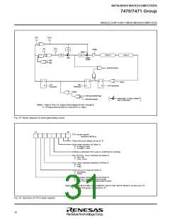
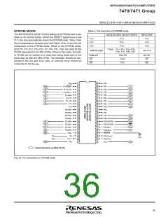
Notes 1 : Latency time is automatically generated upon release from the STP instruction due to the connections of timer 3
and 4.
2 : When the system clock is switched over by restarting clock oscillation, a certain wait time required for oscillation
to stabilize must be inserted by the program.
Fig. 27 Transition of states for the system clock
31

 ETC [ ETC ]