MITSUBISHI MICROCOMPUTERS
7470/7471 Group
SINGLE-CHIP 8-BIT CMOS MICROCOMPUTER
CLOCK GENERATING CIRCUIT
The 7470 group has one internal clock generating circuit and 7471
group has two internal clock generating circuits.
M37470M2-XXXSP
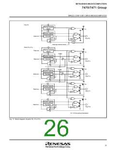
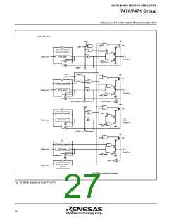
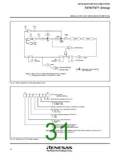
Figure 25 shows a block diagram of the clock generating circuit.
Normally, the frequency applied to the clock input pin XIN divided
by two is used as the internal clock φ. Bit 7 of CPU mode register
can be used to switch the internal clock φ to 1/2 the frequency ap-
plied to the clock input pin XCIN in the 7471 group.
XIN
XOUT
Rd
CIN
COUT
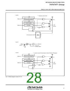
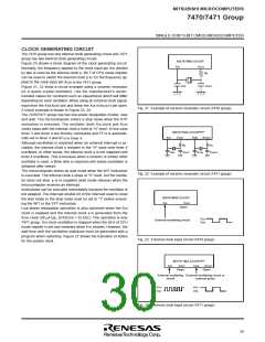
Figure 21, 22 show a circuit example using a ceramic resonator
(or a quartz-crystal oscillator). Use the manufacturer’s recom-
mended values for constants such as capacitance which will differ
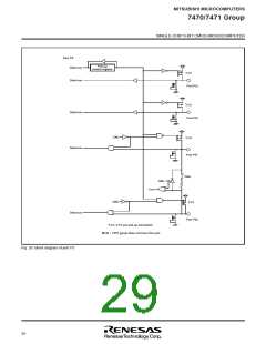
depending on each oscillator. When using an external clock signal,
input from the XIN(XCIN) pin and leave the XOUT(XCOUT) pin open.
A circuit example is shown in Figure 23, 24.
Fig. 21 Example of ceramic resonator circuit (7470 group)
The 7470/7471 group has two low power dissipation modes; stop
and wait. The microcomputer enters a stop mode when the STP
instruction is executed. The oscillator (both XIN clock and XCIN
clock) stops with the internal clock φ held at “H” level. In this case
timer 3 and timer 4 are forcibly connected and FF16 is automati-
cally set in timer 3 and 0716 in timer 4.
M37471M2-XXXSP/FP
XOUT
XCOUT
XIN
XCIN
Although oscillation is restarted when an external interrupt is ac-
cepted, the internal clock φ remains in the “H” state until timer 4
overflows. In other words, the internal clock φ is not supplied until
timer 4 overflows. This is because when a ceramic or similar other
oscillator is used, a finite time is required until stable oscillation is
obtained after restart.
Rd
COUT
Rd
CCOUT
CIN
CCIN
The microcomputer enters an wait mode when the WIT instruction
is executed. The internal clock φ stops at “H” level, but the oscilla-
tor does not stop. φ is re-supplied (wait mode release) when the
microcomputer receives an interrupt.
Fig. 22 Example of ceramic resonator circuit (7471 group)
Instructions can be executed immediately because the oscillator is
not stopped. The interrupt enable bit of the interrupt used to reset
the wait mode or the stop mode must be set to “1” before execut-
ing the WIT or the STP instruction.
M37470M2-XXXSP
XIN
XOUT
Open
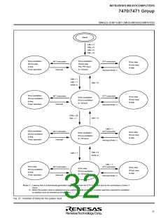
Low power dissipation operation is also achieved when the XIN
clock is stopped and the internal clock φ is generated from the
XCIN clock (30 µA typ. at f(XCIN) = 32 kHz). This operation is only
7471 group. XIN clock oscillation is stopped when the bit 6 of CPU
mode register is set and restarted when it is cleared. However, the
wait time until the oscillation stabilizes must be generated with a
program when restarting. Figure 27 shows the transition of states
for the system clock.
VCC
VSS
External oscillating circuit
Fig. 23 External clock input circuit (7470 group)
M37471M2-XXXSP/FP
XIN
XOUT
XCOUT
XCIN
Open
Open
External oscillating External oscillating circuit or
circuit external pulse
VCC
VSS
VCC
VSS
Fig. 24 External clock input circuit (7471 group)
29

 ETC [ ETC ]