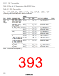
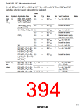
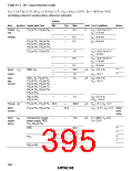
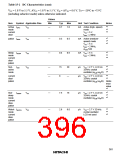
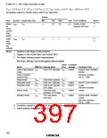
Table 15-2 DC Characteristics (cont)
VCC = 1.8 V to 5.5 V, AVCC = 1.8 V to 5.5 V, VSS = AVSS = 0.0 V, Ta = –20°C to +75°C
(including subactive mode) unless otherwise indicated.
Values
Item
Symbol Applicable Pins
Min
Typ
Max
Unit Test Condition
Notes
3
Stand- ISTBY
by
VCC
—
1.0
5.0
µA 32-kHz crystal
*
*
4
oscillator not used
mode
current
dissi-
pation
3
RAM
data
VRAM
VCC
1.5
—
—
V
*
*
4
retain-
ing
voltage
Notes: 1. Applies to the Mask ROM products.
2. Applies to the HD6473887 and HD6473847.
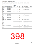
3. Pin states during current measurement.
Pin States during Current Dissipation Measurement
Other Constant-
Pins Voltage Oscillator Pins
Mode
RES Pin Internal State
Active (high-speed) VCC
mode
Only CPU Operates VCC
Halted
System clock oscillator:
Crystal
Active (medium-
speed) mode
Subclock oscillator:
Pin X1 = GND
Sleep mode
VCC
VCC
VCC
Only timers operate VCC
Only CPU Operates VCC
Subactive mode
Subsleep mode
Halted
Halted
System clock oscillator:
Only timers operate, VCC
CPU stops
crystal
Subclock oscillator:
Watch mode
VCC
VCC
Only time base
operates, CPU stops
VCC
Halted
Halted
crystal
Standby mode
CPU and timers
both stop
VCC
System clock oscillator:
crystal
Subclock oscillator:
Pin X1 = GND
4. Excludes current in pull-up MOS transistors and output buffers.
5. When internal step-down circuit is used.
382

 ETC [ ETC ]