13.1.3
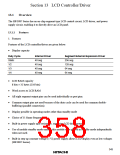
Pin Configuration
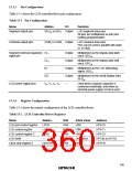
Table 13-1 shows the LCD controller/driver pin configuration.
Table 13-1 Pin Configuration
Name
Abbrev.
I/O
Function
Segment output pins
SEG40 to SEG1 Output
LCD segment drive pins
All pins are multiplexed as port pins
(setting programmable)
Common output pins
COM4 to COM1 Output
LCD common drive pins
Pins can be used in parallel with static
or 1/2 duty
Segment external expansion CL1
signal pin
Output
Output
Output
Output
—
Multiplexed as the display data latch
clock, SEG40
CL2
Multiplexed as the display data shift
clock, SEG39
M
Multiplexed as the LCD alternating
signal, SEG37
DO
Multiplexed as the serial display data,
SEG38
LCD power supply pins
V0, V1, V2, V3
Used when a bypass capacitor is
connected externally, and when an
external power supply circuit is used
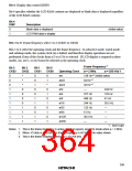
13.1.4
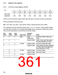
Register Configuration
Table 13-2 shows the register configuration of the LCD controller/driver.
Table 13-2 LCD Controller/Driver Registers
Name
Abbrev.
LPCR
LCR
R/W
R/W
R/W
R/W
R/W
R/W
Initial Value
H'00
Address
H'FFC0
LCD port control register
LCD control register
LCD control register 2
LCD RAM
H'80
H'FFC1
LCR2
—
H'60
H'FFC2
Undefined
H'FF
H'F740 to H'F753
H'FFFB
Clock stop register 2
CKSTPR2
345

 ETC [ ETC ]