9.5.4
Operation
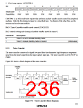
Timer G is an 8-bit timer with built-in input capture and interval functions.
1. Timer G functions
Timer G is an 8-bit up-counter with two functions, an input capture timer function and an interval
timer function.
The operation of these two functions is described below.
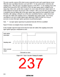
a. Input capture timer operation
When the TMIG bit is set to 1 in port mode register 1 (PMR1), timer G functions as an
input capture timer*.
In a reset, timer mode register G (TMG), timer counter G (TCG), input capture register GF
(ICRGF), and input capture register GR (ICRGR) are all initialized to H'00.
Following a reset, TCG starts incrementing on the ø/64 internal clock.
The input clock can be selected from four internal clock sources by bits CKS1 and CKS0
in TMG.
When a rising edge/falling edge is detected in the input capture signal input from the TMIG
pin, the TCG value at that time is transferred to ICRGR/ICRGF. When the edge selected
by IIEGS in TMG is input, IRRTG is set to 1 in IRR2, and if the IENTG bit in IENR2 is 1
at this time, an interrupt request is sent to the CPU. For details of the interrupt, see 3.3.,
Interrupts.
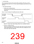
TCG can be cleared by a rising edge, falling edge, or both edges of the input capture signal,
according to the setting of bits CCLR1 and CCLR0 in TMG. If TCG overflows when the
input capture signal is high, the OVFH bit is set in TMG; if TCG overflows when the input
capture signal is low, the OVFL bit is set in TMG. If the OVIE bit in TMG is 1 when these
bits are set, IRRTG is set to 1 in IRR2, and if the IENTG bit in IENR2 is 1, timer G sends
an interrupt request to the CPU. For details of the interrupt, see 3.3., Interrupts.
Timer G has a built-in noise canceler that enables high-frequency component noise to be
eliminated from pulses input from the TMIG pin. For details, see 9.5.3, Noise Canceler.
Note:
* An input capture signal may be generated when TMIG is modified.
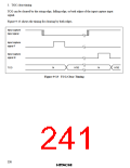
b. Interval timer operation
When the TMIG bit is cleared to 0 in PMR1, timer G functions as an interval timer.
Following a reset, TCG starts incrementing on the ø/64 internal clock. The input clock can
be selected from four internal clock sources by bits CKS1 and CKS0 in TMG. TCG
increments on the selected clock, and when it overflows from H'FF to H'00, the OVFL bit
is set to 1 in TMG. If the OVIE bit in TMG is 1 at this time, IRRTG is set to 1 in IRR2,
and if the IENTG bit in IENR2 is 1, timer G sends an interrupt request to the CPU. For
details of the interrupt, see 3.3., Interrupts.
223

 ETC [ ETC ]