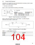
2. Connecting a ceramic oscillator
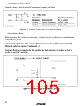
Figure 4-4 shows a typical method of connecting a ceramic oscillator.
C1
OSC1
OSC2
Rf = 1 MΩ ±20%
Rf
Oscillation
frequency Manufacturer
Recommended value
for C1 and C2
C2
1.0 MHz
4.0 MHz
Murata Seisakusho 150 pF ±10%
Murata Seisakusho 30 pF ±10%
Figure 4-4 Typical Connection to Ceramic Oscillator
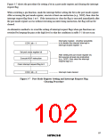
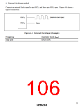
3. Notes on board design
When generating clock pulses by connecting a crystal or ceramic oscillator, pay careful attention
to the following points.
Avoid running signal lines close to the oscillator circuit, since the oscillator may be adversely
affected by induction currents. (See figure 4-5.)
The board should be designed so that the oscillator and load capacitors are located as close as
possible to pins OSC1 and OSC2.
To be avoided
C1
Signal A Signal B
OSC1
OSC2
C2
Figure 4-5 Board Design of Oscillator Circuit
90

 ETC [ ETC ]