4.2
System Clock Generator
Clock pulses can be supplied to the system clock divider either by connecting a crystal or ceramic
oscillator, or by providing external clock input.
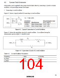
1. Connecting a crystal oscillator
Figure 4-2 shows a typical method of connecting a crystal oscillator.
C1
Rf = 1 MΩ ±20%
OSC1
Rf
Oscillation
frequency Manufacturer
Recommended value
for C1 and C2
OSC2
1.0 MHz
Nihon Denpa Kogyo 27 pF ±10%
Nihon Denpa Kogyo 12 pF ±20%
C2
4.19 MHz
Figure 4-2 Typical Connection to Crystal Oscillator
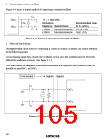
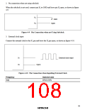
Figure 4-3 shows the equivalent circuit of a crystal oscillator. An oscillator having the
characteristics given in table 4-1 should be used.
CS
LS
RS
OSC1
OSC2
C0
Figure 4-3 Equivalent Circuit of Crystal Oscillator
Table 4-1 Crystal Oscillator Parameters
Frequency
RS (max)
C0 (max)
1 MHz
40 Ω
4.193 MHz
100 Ω
3.5 pF
16 pF
89

 ETC [ ETC ]