Section 4 Clock Pulse Generators
4.1
Overview
Clock oscillator circuitry (CPG: clock pulse generator) is provided on-chip, including both a
system clock pulse generator and a subclock pulse generator. The system clock pulse generator
consists of a system clock oscillator and system clock dividers. The subclock pulse generator
consists of a subclock oscillator circuit and a subclock divider.
4.1.1
Block Diagram
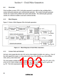
Figure 4-1 shows a block diagram of the clock pulse generators.
øOSC/2
øOSC
OSC1
OSC2
System clock
oscillator
System clock
divider (1/2)
øOSC/128
øOSC/64
øOSC/32
øOSC/16
ø
(fOSC
)
System
clock
ø/2
to
Prescaler S
(13 bits)
divider
ø/8192
System clock pulse generator
øW
øW/2
Subclock
divider
(1/2, 1/4, 1/8)
X1
X2
øW
(fW
øW/4
øW/8
Subclock
oscillator
øSUB
)
øW /2
øW /4
øW /8
to
Prescaler W
(5 bits)
Subclock pulse generator
øW /128
Figure 4-1 Block Diagram of Clock Pulse Generators
System Clock and Subclock
4.1.2
The basic clock signals that drive the CPU and on-chip peripheral modules are ø and øSUB. Four of
the clock signals have names: ø is the system clock, øSUB is the subclock, øOSC is the oscillator
clock, and øW is the watch clock.
The clock signals available for use by peripheral modules are ø/2, ø/4, ø/8, ø/16, ø/32, ø/64, ø/128,
ø/256, ø/512, ø/1024, ø/2048, ø/4096, ø/8192, øW, øW/2, øW/4, øW/8, øW/16, øW/32, øW/64, and
øW/128. The clock requirements differ from one module to another.
88

 ETC [ ETC ]