APEX 20K Programmable Logic Device Family Data Sheet
SRAM configuration elements allow APEX 20K devices to be
reconfigured in-circuit by loading new configuration data into the device.
Real-time reconfiguration is performed by forcing the device into
command mode with a device pin, loading different configuration data,
reinitializing the device, and resuming user-mode operation. In-field
upgrades can be performed by distributing new configuration files.
Configuration Schemes
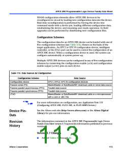
The configuration data for an APEX 20K device can be loaded with one of
five configuration schemes (see Table 115), chosen on the basis of the
target application. An EPC2 or EPC16 configuration device, intelligent
controller, or the JTAG port can be used to control the configuration of an
APEX 20K device. When a configuration device is used, the system can
configure automatically at system power-up.
Multiple APEX 20K devices can be configured in any of five configuration
schemes by connecting the configuration enable (nCE) and configuration
enable output (nCEO) pins on each device.
Table 115. Data Sources for Configuration
Configuration Scheme
Data Source
Configuration device
EPC1, EPC2, EPC16 configuration devices
MasterBlaster or ByteBlasterMV download cable or serial data source
Parallel data source
Passive serial (PS)
Passive parallel asynchronous (PPA)
Passive parallel synchronous (PPS)
JTAG
Parallel data source
MasterBlaster or ByteBlasterMV download cable or a microprocessor
with a Jam or JBC File
For more information on configuration, see Application Note 116
(Configuring APEX 20K, FLEX 10K, & FLEX 6000 Devices.)
f
See the Altera web site (http://www.altera.com) or the Altera Digital
Library for pin-out information.
Device Pin-
Outs
The information contained in the APEX 20K Programmable Logic Device
Family Data Sheet version 3.7 supersedes information published in previous
versions.
Revision
History
Version 3.7 Changes
ꢀ
Added Tables 37 through 43.
Altera Corporation
113

 ETC [ ETC ]