C L A S S
MINIATURE SOLID STATE RELAY
226
RANDOM VOLTAGE TURN ON
CLASS 226
COMPATIBLE WITH TTL GATES.
PRINTED CIRCUIT AND PUSH-ON
UP TO 7 AMPS
SPST—NO
TERMINAL PIN VERSIONS.
DC INPUTS
AC OUTPUTS
UL Recognized
File No. E52197
R
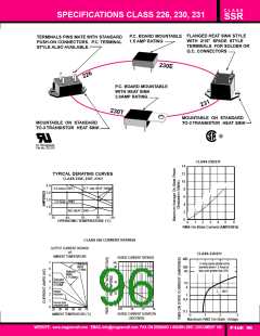
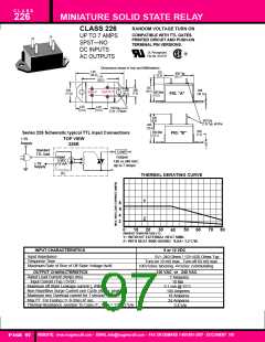
Dimensions shown in Inch and (Millimeters).
1.50
(38.5)
.155
(3.9)
.990 Typ.
(25.1)
1.18
(30.2)
.755
(19.1)
.300
(7.5)
.670
(17.0)
.200
(5.1)
.050
(38.1)
OUTPUT
INPUT
.600 Max
(15.2)
FIG. "A"
.4.92
(12.5)
.4.92
(12.5)
.156 Dia.
(3.8) 2 Places
.340
(8.6)
.940
(23.4)
.600 Max
(15.2)
.062 Dia.
(1.6) Typ. all Pins
.050
(1.3)
Series 226 Schematic typical TTL input Connections
FIG. "B"
TOP VIEW
226R
+ 5V
Supply
Standard
TTL Gate
Load
Input
5 VDC
15 mA
Output
120 or 240 VAC
up to 7 Amps
+ 5V
Supply
R1
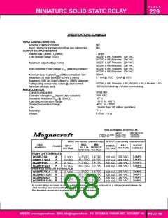
THERMAL DERATING CURVE
Y
8
6
4
2
Z
0
10
30
70
80
20
50
60
40
AMBIENT TEMPERATURE (˚C)
Y= WITHOUT EXTERNAL HEAT SINK.
Z= WITH HEAT SINK HAVING 0 SA= 3.2˚C/W.
INPUT CHARACTERISTICS
5 or 12 VDC
Input Impedance
Response Time
Maximum Rate of Rise of Off State Voltage dv/dt
5V= 240 Ohms / 12V=820 Ohms Typ.
Turn-on 10 mS max., Turn-off 60 mS max.
100V/uSec blocking 4V/uSec commutating
OUTPUT CHARACTERISTICS
Rated Load Current (Amps rms)
120 VAC or 240 VAC
7 Amperes
Input Current (Typ.) 5VDC
10 Ma
Maximum off State Leakage current ID (RMS)
Non-Repetitive Surge Current one Cycle (Amps peak)
Maximum rms Overload current for 1 second
Max I2T For Fusing ( t= 8-3ms) A2 sec
0.1 mA @ 25˚C
100 Amperes
18 Amperes
24 Amperes
3.4˚c/w
Thermal Resistance Junction To Case (TJ , Max.= 1150C) 0c/w
WEBSITE: www.magnecraft.com - EMAIL:info@magnecraft.com - FAX ON DEMAND 1-800/891-2957 - DOCUMENT 100
PAGE 97

 ETC [ ETC ]