C L A S S
SSR
APPLICATION DATA
TRANSFORMERS
PROTECTING THE OUTPUT SWITCH
An SSR is a four layer semiconductor having 3 terminals:
Cathode, Anode and Gate. Normally it blocks current in both the
forward and reverse directions. The SCR is triggered on in the
forward direction by a small gate current. The SCR remains on
until load current decreases to a value less than necessary to
maintain the SCR in the on state. When switching AC, two SSR's
are connected in inverse parallel.
In controlling transformers, the characteristics of the secondary load should
be considered because it reflects the effective load on the SSR. Voltage
transients from secondary load circuits, similarly, are frequently transformed
and can be imposed on the SSR. Transformers present a special problem
in that, depending on the state of the transformer flux at the time of turnoff,
the transformer may saturate during the first half-cycle of subsequent
applied voltage. This saturation can impose a very large current (Com-
monly ten to one hundred times rated primary current) on the SSR and
exceed its half-cycle surge rating.
A Triac also has 3 terminals, like the SCR, it normally blocks
current in both directions; but may be triggered in either direction
by a small gate current
Both SCR's and Triacs are members of the thyristor family.
Therefore, we use this term to denote both devices. There are 4
ways to put a thyristor into a conducting mode. Only one method
is desirable and the other three are the source of most application
problems.
SSR's having random turn-on may have a better chance of survival than a
zero voltage turn-on device for they commonly require the transformer to
support only a portion of the first half-cycle of the voltage. On the other
hand, a random turn-on device will frequently close at the essentially zero
voltage point (start of the half-cycle) and then the SSR must sustain the
worst-case saturation current. A zero voltage turn-on device has the
advantage that it turns on in a known, predictable mode and will normally
immediately demonstrate (dependent on turnoff flux polarity) the worst-case
condition. The use of an oscilloscope is recommended to verify that the
half-cycle surge capability of the SSR is not exceeded. The severity of the
transformer saturation problem varies greatly, dependent on the magnetic
material of the transformer, saturated primary impedance, line impedance,
etc.
The 4 methods of Thyristor turn-on are -
A. Gate Turn-on: By injecting a controlled current into the gate
(the desired method).
B. Forward Breakover Turn-on: A voltage in excess of the
Breakover (or Peak Blocking) voltage across Thyristor.
C. DV/DT turn-on: A voltage which rises faster than the Thyristor
can tolerate, and still remain in the off state.
D. Thermal Turn-on: Allowing the temperature of the thyristor to
go beyond the value sufficient to cause excessive leakage
current, causing turn-on and possible thermal runaway.
A safe rule of thumb in applying an SSR to a transformer primary is to select
an SSR having a half-cycle current surge rating (RMS) greater than the
maximum applied line voltage (RMS) divided by the transformer primary
resistance. The primary resistance is usually easily measured and can be
relied on as a minimum impedance limiting the first half-cycle of inrush
current. The presence of some residual flux plus the saturated reactance of
the primary will then further limit, in the worst case, the half-cycle surge
safely within the surge rating of the SSR.
The last three methods can be protected against as follows. In
those situations where high peak voltage transients occur, effective
protection can be obtained by using metal oxide varistors (MOV).
The MOV is a bidirectional voltage sensitive device that has low
impedance when its design voltage threshold is exceeded.
HEAT SINKING
SELECTING THE PROPER SSR
It is important to select the right size heat sink for your applications.
SSR's will typically generate 1.2 watts per amp of load current.
The maximum junction temperature of the output device is 115˚C.
The total wattage is divided by the thermal resistance to get the
temperature difference between the output device junction and the
ambient temperature. For example a 25 Amp SSR with a 20 Amp
load applied dissipates 24 watts when mounted on a aluminum
plate 6" X 6" X 1/8" with thermal grease applied between the SSR
base and aluminum plate. This combination produces a output
junction temperature rise of 24 watts. 24W times (1˚ c/w relay +
1˚ c/w (heat sink) = a operating temperature of 48˚C.
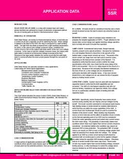
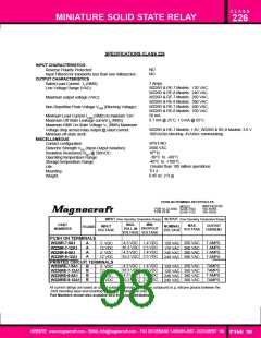
NOMINAL LOAD CURRENT: Initially select a relay whose current rating
exceeds the normal load current. Using the load current vs. temperature
chart for that relay, check the actual current capacity at the ambient
temperature to which the relay will be subjected.
As an example, the chart below shows that a 25 ampere relay provided with
a suitable heat sink can safely carry a maximum of 17 amperes continu-
ously at 40˚C ambient. Since heat degrades the output semiconductor
every effort should be made to keep the operating temperature of the SSR
as low as possible
FUSING
THE SSR has a I2T rating which is a measure of the amount of
energy it can safely handle without damage. The I2T rating of the
fuse is a measure of the amount of energy the fuse will pass to the
SSR. To protect the SSR, the I2T of the Fuse should be less than
that of the SSR. An SSR exposed to a surge greater than its non-
repetitive rating will normally fail as a shorted unit.
25 Amp Styles
40
Mounted on Heat Sink with 1˚c/w
thermal resistance.
(Sink to Ambient)
35
EXPRESSIONS USED IN SPECIFICATIONS
30
dv
dt
equals the maximum permissable rate of change
of voltage in volts/microseconds
25
20
V =
I =
(PF)=
f =
Line Voltage
Load Current
Load Power Factor
Line Frequency
15
6" x 6" x 1/8"
Aluminum
Plate
10
5
Free Air Mounting
L =
C =
R1 & R2 =
Inductance in Henrys
Capacitance in microfarads
Resistance in Ohms
0
20
40
60
80
100
Max. Ambient Temperature (˚C)
WEBSITE: www.magnecraft.com EMAIL:info@magnecraft.com FAX ON DEMAND 1-800/891-2957, DOCUMENT 100
PAGE 95

 ETC [ ETC ]