SERIES
20 AMP GROUND FAULT INTERRUPT (GFI) RELAY
214
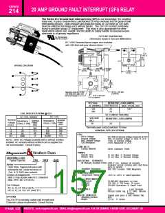
The Series 214 Ground fault interrupt relay (GFI) to our knowledge, the smallest
relay ever, to pass Underwriters Laboratories 20 Amp overload test for ground fault
interrupting devices. Both resistive and Inductive loads of 120 Amps at 120 volts
must be switched ten times each without failure. The 214 GFI is most commonly
found in portable (plug) GFI equipment. This relay is also appropriate for other
applications where size, weight, and the ability to safely handle occasional severe
overloads is of primary importance.
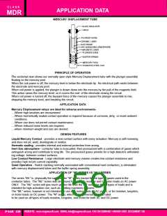
OUTLINE DIMENSIONS
UL Recognized
File No. E13224
Dimensions shown in inch and (Millimeters)
# 17 AWG Stranded tinned copper wire insulated
with .032 thick wall gray silicone rubber
1.37
(34.7)
.839
(21.3)
WIRING DIAGRAM
+.000
- .010
+.000
- .010
C
L
0.30 Max.
(7.62)
.900
.900
(22.8)
(22.8)
1.00
(25.4)
.500
(12.7)
0.70 x .150 slot
(2 places)
Mounting hole # 6-32 thd.
.375 deep min. with .250
full form threads
0.62 x .093 slot
(2 places)
VOLTAGE
AC (50/60HZ) CONTINUOUS
RESISTIVE LOAD (AMPS)
MAX. OVERLOAD
120
240
20
20
120 *
-
COIL SPECIFICATIONS @ 25˚C
DC COIL
DC CONTACT RATING
AC COIL 50/60hZ
VOLTAGE
(DC)
30
RESISTIVE LOAD (AMPS)
Nominal
Nominal
Power
(mA)
Resistance
Ohms ± 10%
Nominal
Power
(mA)
Resistance
Ohms ± 10%
Voltage
(VDC)
20
-
* Normally open contact switched 10 times
30
120
480
6
12
24
115
5
20
80
360
175
90
200
100
50
GENERAL SPECIFICATIONS
COIL
10,000
2000
17
11.5
Pull-in Voltage:
DC: 80% of nominal voltage measured at 25˚C
10% of nominal voltage or more @ 25˚C
110% of nominal voltage
Dropout Voltage:
Max. allowed voltage:
Coil Resistance:
NOTE: Other DC voltages available with or without rectifiers
installed. AC versions without rectifiers can be supplied but
not recommended. Consult Factory
±10% Measured @ 25˚C
CONTACTS
Contact Material:
Silver Cadmium Oxide.
TIMING
Struthers-Dunn
Operate Time:
Release Time:
15 mS Max. @ Nominal Voltage.
15 mS Max. @ Nominal Voltage.
ORDERING CODE
214
HXX
-24D
Typical Type No.
DIELECTRIC STRENGTH
All Mutually Insulated Points:
2000 V rms between all mutually
Insulated current carrying parts and those
parts to ground.
Series
Open Style, Tapped pole piece with
antirotation tab. solder terminals on
.Coil, # 17 AWG wire contacts.
Contact Arrangements
Insulation Resistance:
500 VDC Exceeds 1000 Megohms.
TEMPERATURE
Temperature Rating:
-45˚C to +65˚C @ rated operation.
HXX (1 Pole double make N.O.) Standard
BXX DPST-NO (2 Form A)
LIFE EXPECTANCY
Mechanical:
10,000,000 Operations no load
120 VAC @ 120 Amps, 10 cycles
100,000 Operations @ Rated Load.
Overload:
Electrical:
Coil Voltages
AC: 6, 12, 24, 120 ( Add A)
DC: 6, 12, 24, 110-125 (Add "D")
TERMINALS
Coil
Load Terminals
Pierced Solder lug # 17 AWG. Silicone
Rubber.
Tapped pole piece & anti rotation Tab.
Any
MISCELLANEOUS
Mounting position:
Weight:
OPTIONS
2.5 oz. 71 Grams
The 214 GFI is normally custom built to meet each
Customers unique requirements. Consult Factory.
PART NUMBER SHOWN ALSO AVAILABLE THRU STOCKING DISTRIBUTION
WEBSITE: www.magnecraft.com EMAIL:info@magnecraft.com FAX ON DEMAND 1-800/891-2957, DOCUMENT 100
PAGE 157

 ETC [ ETC ]