TIME DELAY
RELAYS
& SENSORS
APPLICATION DATA
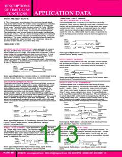
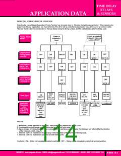
SELECTING A TIMER'S MODE OF OPERATION
Selecting the correct Mode of operation (Timing Function) can be easily done by following the ladder diagram below. When selecting the
proper relay for your application, you must determine if the timer will be controlled by input power only, or the use of an external switch.
The next item to take into consideration is the load status during the timing cycle(s), and the contact status after the timing cycle.
Power is supplied
to Input & External
Switch ON/OFF
Power is
supplied to
Input
Timing Starts
When?
Output status
During Timing
cycle (s).
OFF
ON
ON
OFF
ON
ON
ON/OFF
ON
NOTE 1
NOTE 3
NOTE 4
Load Status at
end of First
Timing cycle.
ON
OFF
OFF
ON
OFF
OFF
NOTE 2
Load Status at
end of Second
Timing cycle.
OFF
OFF
NOTE 5
NOTE 2
TRUE
OFF
DELAY
BATCH
CONTROL
(INTERVAL)
ONE
SHOT
ON/OFF
DELAY
REPEAT
CYCLE
OFF
DELAY
ON
DELAY
Timer Type.
211PROGX
211 SOX
67 SOX
326X
388 SOX
236X
211PROGX
211 SRX
237X
Applicable
Time delay
relays
that apply
to Mode of
Operation
211PROGX
238X
211PROGX
388 SRX
222 PFX
238ABX
327X
388 SRX
247XBX
287X
246XBX
286X
NOTES:
1. Momentary power supplied to the input. Input power not required for timing cycle.
2. Continues to repeat timing cycles until power is removed from input
3. Upon closure of External switch, relay contacts switch and time period begins. The timing is not affected by the duration
of the External switch closure.
4. External switch is maintained closed, relay contacts switch at the end of first timing cycle.
5. External switch is maintained open for second timing cycle.
Footnote: ON = Relay coil energized, contacts switched. OFF = Relay coil de-energized, contacts in normal position.
WEBSITE: www.magnecraft.com EMAIL:info@magnecraft.com FAX ON DEMAND 1-800/891-2957, DOCUMENT 100
PAGE 114

 ETC [ ETC ]