For an oversampling factor of four, the filter executes the above
sequence at four times the symbol rate (60 MHz in PLL mode).
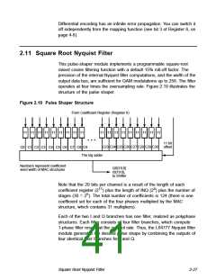
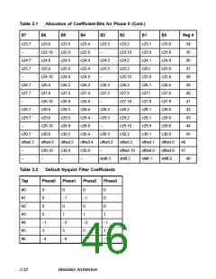
Each multiply accumulator (MAC)-structure contains 31 multipliers whose
outputs add up to the desired result. The pulse shaper module connects
one input of each multiplier to a delayed version of the filter input data;
the other multiplier input is connected to one of four coefficient registers
through a multiplexer. The pulse shaper clocks the delay line for IData
and QData with the symbol clock rate. The coefficient and multiplier
width are as described below.
The pulse shaper interprets all data as two’s complement. Each MAC-
structure contains an additional input to the adder array to allow for the
addition of an 11-bit value to compensate for an offset. The pulse shaper
treats these offset coefficients like regular coefficients, except that it adds
them directly to the MAC outputs. There is one offset coefficient for each
phase.
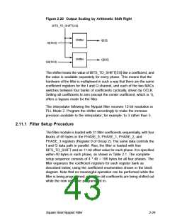
The shifter block adjusts the internally generated filter result to
accommodate the limited range of the internal D/A-converter. The
standard mapping after reset is a five-bit shift to the right, which means
IS[5] to I[0], IS[6] to I[1] and so on. The shifter treats the Q-branch
accordingly.
By applying a value different from zero to the BITS_TO_SHIFT[3:0] input
of the shifter (using Register 0), the shifter connects IS to I, and QS to
Q, so that the lowest bits of IS and QS are truncated, while the more
significant bits are hooked to the I and Q outputs. The BITS_TO_SHIFT
input can assume a maximum value of 15, thus mapping IS[15] to I[0],
IS[16] to I[1], and so on. The filter output value is not limited to maximum
positive or negative values before shifting, so it is the user’s responsibility
to download coefficients and an appropriate shifting value to avoid output
overflow and underflow. Figure 2.20 illustrates the output scaling by an
arithmetic shift to the right.
2-28
Modulator Architecture

 ETC [ ETC ]