CY7C1347C/GVT71128DA36
CY7C1327C/GVT71256DA18
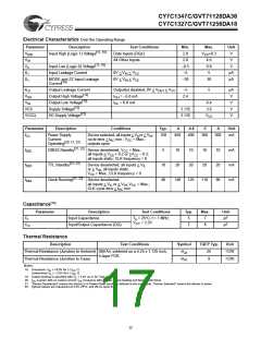
Electrical Characteristics Over the Operating Range
Parameter
Description
Test Conditions
Data Inputs (DQx)
All Other Inputs
Min.
2.0
Max.
V +0.3
CC
Unit
V
[12, 18]
V
Input High (Logic 1) Voltage
IHD
IH
Il
V
V
2.0
4.6
V
[12, 18]
Input Low (Logic 0) Voltage
Input Leakage Current
–0.5
–5
0.8
5
V
IL
0V < V < V
µA
µA
I
IN
CC
IL
MODE and ZZ Input Leakage
0V < V < V
–30
30
I
IN
CC
[19]
Current
IL
Output Leakage Current
Output(s) disabled, 0V < V
< V
CC
–5
5
µA
V
O
OUT
[12]
V
Output High Voltage
I
I
= –5.0 mA
2.4
OH
OH
OL
[12]
V
Output Low Voltage
= 8.0 mA
0.4
3.6
V
OL
[12]
VCC
Supply Voltage
3.135
3.135
V
[12]
VCCQ
I/O Supply Voltage
V
V
CC
Parameter
Description
Conditions
Device selected; all inputs < V or > V ;
Typ.
-4
-4.4
-5
-6
Unit
I
I
I
I
Power Supply
Current:
150
450
400
360
300
mA
CC
IL
IH
cycle time > t min.; V = Max.;
KC
CC
[20, 21, 22]
Operating
outputs open
[21, 22]
CMOS Standby
Device deselected; V = Max.;
5
10
10
10
10
20
90
mA
mA
mA
SB2
SB3
SB4
CC
all inputs < V + 0.2 or >V – 0.2;
SS
CC
all inputs static; CLK frequency = 0
[21, 22]
TTL Standby
Device deselected; all inputs < V
10
40
20
20
20
IL
or > V ; all inputs static;
IH
V
= Max.; CLK frequency = 0
CC
[21, 22]
Clock Running
Device deselected;
all inputs < V or > V ; V = Max.;
140
125
110
IL
IH CC
CLK cycle time > t min.
KC
Capacitance[14]
Parameter
Description
Test Conditions
Typ.
Max.
Unit
C
C
Input Capacitance
T = 25°C, f = 1 MHz,
5
7
7
8
pF
pF
I
A
V
= 3.3V
CC
Input/Output Capacitance (DQ)
O
Thermal Resistance
Description
Test Conditions
Symbol
TQFP Typ.
Unit
Thermal Resistance (Junction to Ambient) Still Air, soldered on a 4.25 x 1.125 inch,
Θ
25
9
°C/W
°C/W
JA
JC
4-layer PCB
Thermal Resistance (Junction to Case)
Θ
Notes:
18. Overshoot: VIH ≤ +6.0V for t ≤ tKC /2.
Undershoot:VIL ≤ –2.0V for t ≤ tKC /2.
19. Output loading is specified with CL = 5 pF as in AC Test Loads.
20. ICC is given with no output current. ICC increases with greater output loading and faster cycle times.
21. “Device Deselected” means the device is in Power-Down mode as defined in the truth table. “Device Selected” means the device is active.
22. Typical values are measured at 3.3V, 25°C, and 20-ns cycle time.
17

 ETC [ ETC ]