CY7C1347C/GVT71128DA36
CY7C1327C/GVT71256DA18
[15, 16]
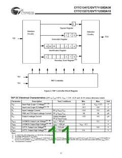
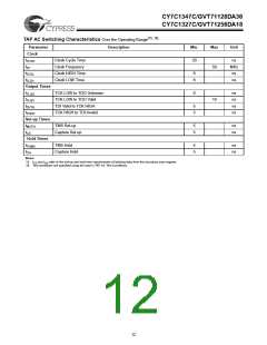
TAP AC Switching Characteristics Over the Operating Range
Parameter
Clock
Description
Min.
Max
Unit
t
f
t
t
Clock Cycle Time
Clock Frequency
Clock HIGH Time
Clock LOW Time
20
ns
MHz
ns
THTH
TF
50
8
8
THTL
TLTH
ns
Output Times
t
t
t
t
TCK LOW to TDO Unknown
TCK LOW to TDO Valid
TDI Valid to TCK HIGH
TCK HIGH to TDI Invalid
0
ns
ns
ns
ns
TLQX
TLQV
DVTH
THDX
10
5
5
Set-up Times
t
TMS Set-up
5
5
ns
ns
MVTH
t
Capture Set-up
CS
Hold Times
t
t
TMS Hold
5
5
ns
ns
THMX
Capture Hold
CH
Notes:
15. CS and tCH refer to the set-up and hold time requirements of latching data from the boundary scan register.
16. Test conditions are specified using the load in TAP AC Test Conditions.
t
12

 ETC [ ETC ]