Register Description
3.1.3
PM2_CTL—ACPI Power Control 2 Control Register
I/O Address:
Default Value:
Access:
0022h
00h
Read/Write
8 bits
Size:
This register is used to disable both the PCI and AGP arbiters in the 82443BX to prevent any
external bus masters from acquiring the PCI or AGP bus. Any currently running PCI cycles will
terminate properly.
Accesses to this register are controlled by the Power Management Control Register (Offset 7Ah).
When bit 6 of the PMCR is set to ‘1’, the ACPI Register at I/O location 0022h is enabled. When bit
6 is set to ‘0’, I/O accesses to location 0022h are forwarded to PCI or AGP (if within programmable
IO range).
Bit
Description
7:1
Reserved
Primary PCI and AGP Arbiter Request Disable (ARB_DIS). When this bit is set to 1, the
82443BX will not respond to any PCI REQ# signals, AGP requests, or PHOLD# from PIIX4E going
active until this bit is set back to 0. Only External AGP and PCI requests are masked from the
arbiters. If the PIIX is in passive release mode, masking will not occur until an active release is seen
via PHLDA# assertion. This prevents possible deadlock.
0
ARB_DIS has no effect on AGP side band signals or AGP data transfer requests.
3.2
PCI Configuration Space Access
The 82443BX implementation manifests two PCI devices within a single physical component
body:
• Device 0 = Host-to-PCI Bridge = PCI bus #0 interface, Main Memory Controller, Graphics
Aperture controller, 82443BX specific AGP control registers.
• Device 1 = Host-to-AGP interface = “Virtual” PCI-to-PCI Bridge, including AGP address
space mapping, normal PCI interface, and associated AGP sideband signal control.
Corresponding configuration registers for both devices are mapped as devices residing on PCI (bus
0). Configuration register layout and functionality for the Device #0 should be inspected carefully,
as new features added to the 82443BX initiated a reasonable level of change relative to other
proliferation’s of the Pentium® Pro processor AGPsets (i.e. 440FX, 440LX). Configuration
registers of the 82443BX Device #1 are based on the normal configuration space template of a PCI-
to-PCI Bridge as described in the PCI to PCI Bridge Architecture Specification.
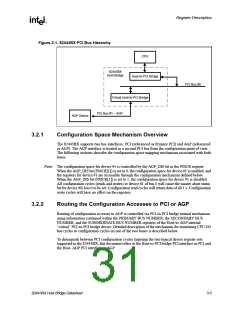
Figure 3-1shows the PCI bus hierarchy for the 82443BX). In the PCI bus hierarchy, the primary
PCI bus is the highest level bus in the hierarchy and is PCI bus #0. The PCI-to-PCI bridge function
provides access to the AGP/PCI bus 0. This bus is below the primary bus in the PCI bus hierarchy
and is represented as PCI Bus #1.
3-4
82443BX Host Bridge Datasheet

 ETC [ ETC ]