600031 Rev. 7/23/02
Preliminary Information
Page 5
+48V
+15
R6
6k8
C6
C4
In-
R3
2
8
100n
-In
51R
7
47u
C1
470p
D3
1N5818
D5
1N5818
RG2
R1
1k
V+
Out
6
R5
6k8
RG
Out
Ref
C2
470p
D6
1N5818
D4
1N5818
1
3
U1
5
V-
RG1
+In
C5
47u
In+
THAT 1510
R4
4
51R
C9
100n
C3
47p
R2
1k
D1
D2
1N757
1N757
-15
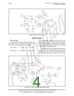
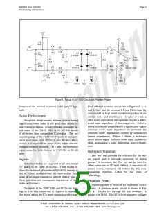
Figure 4. Typical 1510 / 1512 Circuit with Phantom Power
tempco of the internal resistors ( 20 ppm/°C typi-
cal).
Four different schemes are shown in Figures 2, 3, 4,
and 5. Note that the values of R1 and R2 in these fig-
ures should be kept small to minimize pickup of un-
wanted noise and interference. A value of 1 kW is
often used, since some microphones require a differ-
ential input impedance of this magnitude. Unfortu-
nately, one would usually desire a significantly higher
common mode input impedance to minimize the
common mode degradation caused by unbalanced
source impedances. Figure 5 shows a technique
which allows higher common mode input impedance
while maintaining a lower differential source imped-
ance.
Noise Performance
Thoughtful design results in these devices having
significantly lower noise at low gains than similar IC
microphone preamps. At zero dB gain, equivalent in-
put noise of the THAT 1510 is 55 nV/ÖHz, nearly
6 dB better than competitive IC designs. The un-
usual topology of the THAT 1512 results in an equiv-
alent input noise of 34 nV/ÖHz at zero dB gain, which
makes it comparable to some of the better discrete
designs currently available. At 1 kHz, the equivalent
input noise for both devices is 1 nV/ÖHz at 60 dB
gain.
Reference Terminal
The "Ref" pin provides the reference for the out-
put signal, and is normally connected to analog
ground. If necessary, the "Ref" pin can be used for
offset correction or DC level shifting. A non-zero ref-
erence source resistance will reduce the IC's com-
mon-mode rejection (CMR) by the ratio of
Inputs
Protection diodes are employed at all pins except
V+ and V- of the THAT 1510/1512. These diodes re-
duce the likelihood of accidental ESD/EOS damage to
the IC. Other diodes across the base-emitter junc-
tions of the input transistors prevent reverse bias of
these junctions and consequent degradation of their
noise performance.
10 kW/RREF
.
Phantom Power
Phantom power is required for condensor micro-
phones. A phantom power circuit is shown in Fig-
ure 4. Diodes D1 through D6 are necessary to
protect the THAT 1510/1512 from transient voltages
The inputs of the THAT 1510 and1512's are float-
ing, so a dc bias connection is required to maintain
the inputs within the IC's input common-mode range.
THAT Corporation; 45 Sumner Street; Milford, Massachusetts 01757-1656; USA
Tel: +1 508 478-9200; Fax: +1 508 478-0990; Web: www.thatcorp.com

 ETC [ ETC ]