Page 4
THAT 1510 / 1512 Microphone Preamplifier
Preliminary Information
+15
C6
-In
+In
100n
7
2
8
-In
RG2
C1
V+
R1
1k
470p
Out
6
Out
Ref
RG
C2
470p
1
3
U1
THAT
1510/1512
5
V-
4
RG1
+In
C9
R2
1k
C3
47p
100n
-15
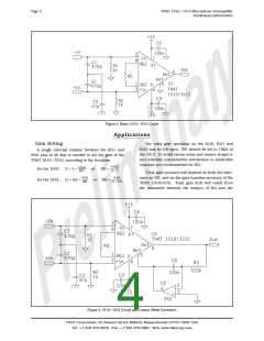
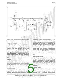
Figure 2. Basic 1510 / 1512 Circuit
Applications
Gain Setting
For unity gain operation on the 1510, RG1 and
RG2 may be left open. RG should be set to 10kW in
the 1512. To avoid excess noise and ensure tempera-
ture stability, non-inductive wirewound or metal-film
resistors are recommended for RG.
A single external resistor between the RG1 and
RG2 pins is all that is needed to set the gain of the
THAT 1510 / 1512, according to the formulae
10 kW
RG =
G - 1
10kW
RG
for the 1510:
for the 1512:
G = 1 +
or
Total gain accuracy will depend on both the toler-
ance on RG, and on the gain equation accuracy of the
THAT 1510/1512. Total gain drift will result from
the mismatch between the tempco of RG and the
5 kW
RG
5 kW
G = 0.5 +
or RG =
G - 0.5
+15
C6
-In
+In
100n
7
2
8
-In
RG2
C1
U1
V+
R1
1k
470p
THAT 1510/1512
Out
Out
RG
6
Ref
C2
470p
1
3
5
RG1
+In
V-
4
C8
R3
510k
R2
1k
100n
C9
C3
47p
U2
2
100n
6
3
-15
353
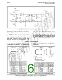
Figure 3. 1510 / 1512 Circuit with Output Offset Correction
THAT Corporation; 45 Sumner Street; Milford, Massachusetts 01757-1656; USA
Tel: +1 508 478-9200; Fax: +1 508 478-0990; Web: www.thatcorp.com

 ETC [ ETC ]