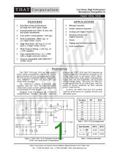
Page 2
THAT 1510 / 1512 Microphone Preamplifier
Preliminary Information
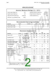
SPECIFICATIONS1
Absolute Maximum Ratings (TA = 25°C)
Positive Supply Voltage (VCC
Negative Supply Voltage (VEE
Output Short-Circuit Duration (tSH
Lead Temp. (TLEAD) (Soldering 10 sec)
)
+20 V
-20 V
Operating Temperature Range (TOP
)
-40 to +85°C
-40 to +125°C
150°C
)
Storage Temperature Range (TST
Junction Temperature (TJ)
)
)
Continuous
260 °C
Recommended Operating Conditions
Parameter
Symbol
VCC
Conditions
Min
+5
Typ
Max
+20
Units
V
Positive Supply Voltage
Negative Supply Voltage
VEE
-5
-20
V
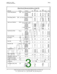
Electrical Characteristics2
1510
Typ Max
1512
Typ Max
Parameter
Symbol
ICC, |IEE
Conditions
Min
Min
Units
Supply Current
|
No signal
CC = |VEE| = 20V
—
—
6.1
—
8.2
8.4
—
—
6.1
—
8.2
8.4
mA
mA
V
Input Bias Current
Input Offset Current
IB
No signal; Either input
connected to GND
—
8.6
25
—
8.6
25
mA
IB-OFF
No signal
—
—
2.5
—
—
2.5
mA
Output Referred Offset Voltage VosOR
Input Referred Offset Voltage
No Signal, VCM=0
60 dB gain
—
—
—
—
50
1.2
—
—
—
—
25
1.2
mV
mV
VosIR
Input Voltage Range
Common Mode
VIN-CM Common mode, all gains
—
—
13
13
—
—
—
—
13
13
—
—
V
V
Normal Mode
VIN-UNBAL
Unbalanced
One input to GND, 0dB gain
Differential Gain
Gdiff
0
—
8
70
—
—
—
0
—
8
60
—
—
—
dB
V
Ref Input Voltage Range
Ref Input Impedance
Ref Input Gain to Output
Input Impedance
—
—
—
—
—
—
10
0
15
0
kW
dB
ZIN-DIFF
Differential
0dB gain
—
—
—
—
32||1.9
32||2.0
32||2.5
29||8.0
—
—
—
—
—
—
—
—
37||1.9
37||2.0
36||3.1
31||13.9
—
—
—
—
MW||pF
MW||pF
MW||pF
MW||pF
20dB gain
40dB gain
60dB gain
Common mode
all gains
ZIN-CM
—
8||7.7
—
—
9||7.7
—
MW||pF
1. All specifications are subject to change without notice.
2. Unless otherwise noted, VCC = +15V, VEE = -15V, TA=25°C,
THAT Corporation; 45 Sumner Street; Milford, Massachusetts 01757-1656; USA
Tel: +1 508 478-9200; Fax: +1 508 478-0990; Web: www.thatcorp.com

 ETC [ ETC ]