<ꢀ5ꢁꢀꢂꢃ<ꢀ.ꢁꢀꢂ
'PJCPEGFꢄ<ꢁꢀꢂꢄ/KETQRTQEGUUQT
ZiLOG
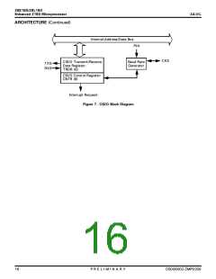
2+0ꢄ&'5%4+26+105ꢄꢈ%QPVKPWGFꢉ
ways recognized at the end of an instruction, regardless of
the stateoftheinterrupt-enableflip-flops. Thissignalforces
CPU execution to continue at location 0066H.
6'0&ꢂꢎꢄ6'0&ꢁꢆ Transfer End 0 and 1 (Outputs, active
Low). This output is asserted active during the most recent
94+6' cycle of a DMA operation. It is used to indicate the
endofthe blocktransfer.6'0&ꢀ is multiplexed with%-#ꢄ.
2*+ꢆꢄSystem Clock (Output). The output is used as a refer-
ence clock for the MPU and the external system. The fre-
quency of this output may be one-half, equal to, or twice
the crystal or input clock frequency.
6'56ꢆꢄTest (Output, not in DIP version). This pin is for test
and should be left open.
6
ꢆꢄTimer Out (Output). 6
is the output from PRT
4&ꢆꢄRead (Output, active Low, 3-state). 4& indicates that
the CPU wants to read data from either memory or an I/O
device. TheaddressedI/Oormemorydeviceshoulduse this
signal to gate data onto the CPU data bus.
channel 1. This line is multiplexed with #ꢄꢆ of the address
bus.
6:#ꢂꢎꢄ6:#ꢁꢆꢄTransmit Data 0 and 1 (Outputs). These sig-
nalsarethetransmitteddatafromtheASCIchannels. Trans-
mitted data changes are with respect to the falling edge of
the transmit clock.
4(5*ꢆ Refresh (Output, active Low). Together with/4'3,
4(5* indicates that the current CPU machine cycle and the
contents of the address bus should be used for refresh of dy-
namic memories. The low-order 8 bits of the address bus
(#ꢊ #ꢀ) containthe refreshaddress.This signalis analogous
to the REF signal of the Z64180.
6:5ꢆꢄClocked Serial Transmit Data (Output). This line is
the transmitted data from the CSI/O channel.
9#+6. Wait (Input, active Low). 9#+6 indicates to the
MPU that the addressed memory or I/O devices are not
ready for data transfer. This input is sampled on the falling
edge of 6ꢂ (and subsequent 9#+6 states). If the input is
sampled Low, then the additional 9#+6 states are inserted
until the 9#+6 input is sampled High, at which time exe-
cution continues.
465ꢂꢆ Request to Send 0 (Output, active Low); a program-
mable MODEM control signal for ASCI channel 0.
4:#ꢂꢎꢄ4:#ꢁꢆꢄReceive Data 0 and 1 (Input). These signals
are the receive data for the ASCI channels.
4:5ꢆꢄClocked Serial Receive Data (Input). This line is the
receivedatafortheCSI/Ochannel. RXSismultiplexedwith
the %65ꢄ signal for ASCI channel 1.
94.94+6'(Output,activeLow, 3-state).94indicatesthat
the CPU data bus holds valid data to be stored at the ad-
dressed I/O or memory location.
56ꢆꢄStatus (Output). This signal is used with the /ꢄ and
*#.6 output todecodethestatusof theCPUmachinecycle.
See Table 3.
:6#.ꢆꢄCrystal Oscillator Connection (Input). This pin
should be left open if an external clock is used instead of a
crystal. TheoscillatorinputisnotaTTLlevel(seeDCChar-
acteristics).
6CDNG ꢋꢆ 5VCVWUꢄ5WOOCT[
56 *#.6 /ꢁ 1RGTCVKQP
Several pins are used for different conditions, depending on
the circumstance.
ꢀ
ꢄ
ꢄ
ꢄ
ꢀ
ꢀ
%27ꢅ1RGTCVKQPꢅꢈꢄUVꢅ1REQFGꢅ(GVEJꢉ
%27ꢅ1RGTCVKQPꢅꢈꢂPFꢅ1REQFGꢅCPFꢅꢍTFꢅ
1REQFGꢅ(GVEJꢉ
ꢄ
ꢄ
ꢄ
%27ꢅ1RGTCVKQPꢅꢈ/%ꢅ'ZEGRVꢅ1REQFGꢅ
(GVEJꢉ
ꢀ
ꢀ
ꢄ
:
ꢀ
ꢀ
ꢄ
ꢀ
ꢄ
&/#ꢅ1RGTCVKQP
*#.6ꢅ/QFG
5.''2ꢅ/QFGꢅꢈ+PENWFKPIꢅ5;56'/ꢅ
5612ꢅ/QFGꢉ
Notes:
:ꢅꢐꢅ&QꢅPQVꢅECTGꢑ
/%ꢅꢐꢅ/CEJKPGꢅ%[ENGꢑ
ꢄꢂ
2ꢅ4ꢅ'ꢅ.ꢅ+ꢅ/ꢅ+ꢅ0ꢅ#ꢅ4ꢅ;
&5ꢀꢀꢁꢀꢀꢂꢃ</2ꢀꢂꢀꢀ

 ZILOG [ ZILOG, INC. ]