eZ80L92 MCU
Product Specification
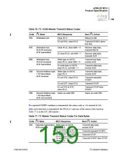
142
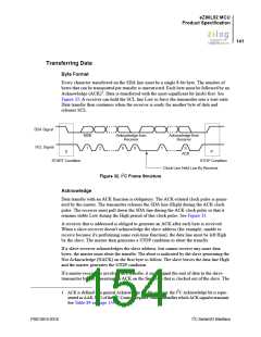
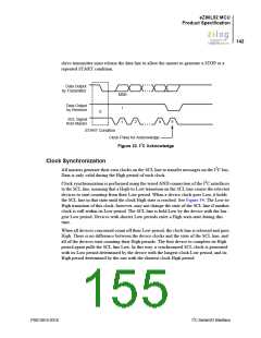
slave-transmitter must release the data line to allow the master to generate a STOP or a
repeated START condition.
Data Output
by Transmitter
MSB
Data Output
by Receiver
1
S
SCL Signal
from Master
1
2
8
9
START Condition
Clock Pulse for Acknowledge
2
Figure 33. I C Acknowledge
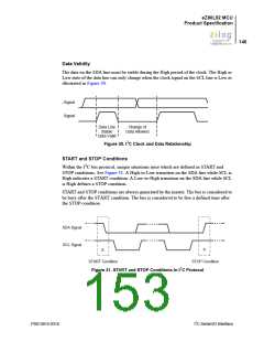
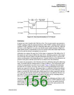
Clock Synchronization
All masters generate their own clocks on the SCL line to transfer messages on the I2C bus.
Data is only valid during the High period of each clock.
Clock synchronization is performed using the wired AND connection of the I2C interfaces
to the SCL line, meaning that a High-to-Low transition on the SCL line causes the relevant
devices to start counting from their Low period. When a device clock goes Low, it holds
the SCL line in that state until the clock High state is reached. See Figure 34. The Low-to-
High transition of this clock, however, may not change the state of the SCL line if another
clock is still within its Low period. The SCL line is held Low by the device with the lon-
gest Low period. Devices with shorter Low periods enter a High wait-state during this
time.
When all devices concerned count off their Low period, the clock line is released and goes
High. There is no difference between the device clocks and the state of the SCL line, and
all of the devices start counting their High periods. The first device to complete its High
period again pulls the SCL line Low. In this way, a synchronized SCL clock is generated
with its Low period determined by the device with the longest clock Low period, and its
High period determined by the one with the shortest clock High period.
PS013015-0316
I2C Serial I/O Interface

 ZILOG [ ZILOG, INC. ]