ZL50022
Data Sheet
Performance Characteristics Notes
† Characteristics are over recommended operating conditions unless otherwise stated.
‡ Typical figures are at 25°C, VDD_CORE at 1.8 V and VDD_IO at 3.3 V and are for design aid only: not guaranteed and not subject to production
testing.
1. Jitter on master clock input (XIN) is 100 ps pp or less.
2. Jitter on reference input (REF0-3) is 2 ns pp or less.
3. Normal Mode selected.
4. Holdover Mode selected.
5. Freerun Mode selected.
6. Jitter is measured without an output filter.
7. Accuracy of master clock input (XIN) is 0 ppm.
8. Accuracy of master clock input (XIN) is 100 ppm.
9. Capture range is +/-260 ppm; inaccuracy of XIN shifts this range.
10. Phase alignment speed (phase slope) is programmed to 7 ns/125µs.
11. Any input reference switch or state switch (i.e. REF0 to REF3, Normal to Holdover, etc.).
12. Multi-period near limits and far limits are programmed to +/-64.713ppm & +/-82.487ppm respectively. (ST4_LIM = 1)
13. Multi-period near limits and far limits are programmed to +/-240ppm & +/-250ppm respectively. (ST4_LIM = 0)
14. 30 pF load on output pin.
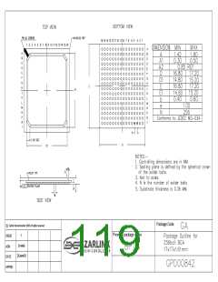
118
Zarlink Semiconductor Inc.

 ZARLINK [ ZARLINK SEMICONDUCTOR INC ]