P
R
E
L
I
M
I
N
A
R
Y
I
N
F
O
R
M
A
T
I
O
N
XpressFlow-2020 Series –
Ethernet Switch Chipset
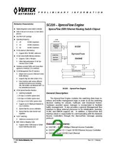
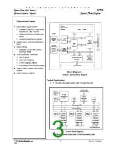
SC220
XpressFlow Engine
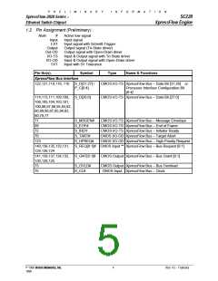
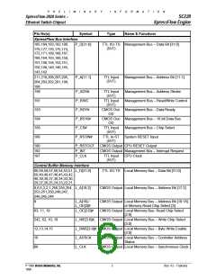
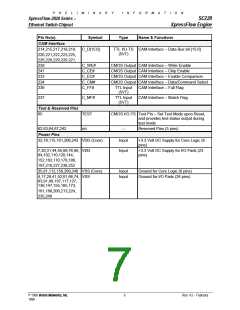
1.2 Pin Assignment (Preliminary)
Note:
#
Input
Active low signal
Input signal
I-ST
Output
Input signal with Schmitt-Trigger
Output signal (Tri-State driver)
Out-OD
I/O-TS
I/O-OD
5VT
Output signal with Open-Drain driver
Input & Output signal with Tri-State driver
Input & Output signal with Open-Drain driver
Input with 5V Tolerance
Pin No(s).
XpressFlow Bus Interface
Symbol
Type
Name & Functions
122,121,119,118, 116 S_D[31:27] /
P_C[0:4]
CMOS I/O-TS XpressFlow Bus – Data Bit [31:28] or
Processor Interface Configuration Bit
[0:4]
114,113,111,109,108, S_D[26:0]
106,105,104,103,101,
CMOS I/O-TS XpressFlow Bus – Data Bit [27:0]
100,98,97,96,95,93,92,
90,89,88,87,85,84,82,
80,79,77
71
69
72
70
123
S_MSGEN#
S_EOF#
CMOS I/O-TS XpressFlow Bus – Message Envelope
CMOS I/O-TS XpressFlow Bus – End of Frame
CMOS I/O-TS XpressFlow Bus – Initiator Ready
CMOS I/O-OD XpressFlow Bus – Target Abort
CMOS I/O-OD XpressFlow Bus – High Priority Request
S_IRDY
S_TABT#
S_HPREQ#
140,138,135,133,131, S_REQ[8:1]# CMOS Input ** XpressFlow Bus – Bus Request [8:1]
129,126,124
141,139,137,134,132, S_GNT[8:1]# CMOS Output XpressFlow Bus – Bus Grant [8:1]
130,128,125
73
75
S_OVLD#
S_CLK
CMOS Output XpressFlow Bus – Bus Overload
CMOS Input XpressFlow Bus – Clock
© 1998 Vertex Networks, Inc.
4
Rev. 4.5 – February
1999

 ZARLINK [ ZARLINK SEMICONDUCTOR INC ]