MVTX2801
Data Sheet
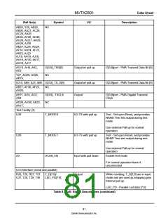
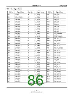
Ball No(s)
Symbol
T_D[11:8]/
I/O
Description
P27, R26, R30, R29
Output
While resetting, T_D[11:8] are in input
mode and are used as strapping pins.
Internal pull up
LED_PT[3:0]
LED_PR[3:0] - Parallel Led port
selection [3:0]
P26, P30, P29, P28, T_D[15:12]/
LED_PT[7:4]
Output
While resetting, T_D[15:12] are in
input mode and are used as strapping
pins. Internal pull up
LED_PR[7:4] - No Meaning
V29
V30
LED_CLK0/
LED_PT[8]
Output
Output
LED_CLK0 - LED Serial Interface
Output Clock
LED_PT[8] - Parallel Led port sel [8]
LED_BLINK/
While resetting, LED-BLINK is in input
mode and is used as strapping pin.
1: No Blink,
LED_DO/ LED_PT[9]
0: Blink. Internal pull up.
LED_DO - LED Serial Data Output
Stream
LED_PT[9] - Parallel Led port sel [9]
V28
LED_PM/
Output with pull up
While resetting, LED_PM is in input
mode and is used as strapping pin.
Internal pull up.
LED_SYNCO#
1: Enable parallel interface,
0: enable serial interface.
LED_SYNCO# - LED Output Data
Stream Envelop
System Clock, Power, and Ground Pins
A16
U26
U30
B1
S_CLK
S_RST#
RESOUT#
DEV_CFG[0]
DEV_CFG[1]
Input
Input - ST
Output
Input w/ pull down
Input w/ pull down
Power core
System Clock at 133 MHz
Reset Input
Reset PHY
Not used
Not used
B28
AE7, AE9, F10, F21, VDD
F22, F9, G25, G6,
J25, J6, K25, K6,
AA25, AA6, AB25,
AB6, AD25, AE10,
AE21, AE22
+2.5 Volt DC Supply
Table 8 - Ball- Signal Descriptions (continued)
82
Zarlink Semiconductor Inc.

 ZARLINK [ ZARLINK SEMICONDUCTOR INC ]