YDA138
■Description of operating functions
●Digital Amplifier Function
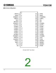
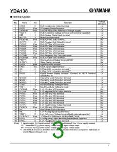
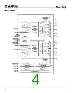
YDA138 has digital amplifiers with analog input, PWM pulse output, Maximum output of 10W (RL=8Ω)×2ch.
Distortion of PWM pulse output signal and noise of the signal is reduced by adopting “Pure Pulse Direct Speaker Drive
Circuit”
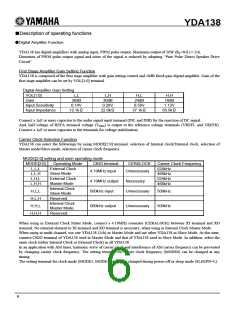
First Stage Amplifier Gain Setting Function
YDA138 is composed of the first stage amplifier with gain setting control and 18dB fixed-gain digital amplifier. Gain of the
first stage amplifier can be set by VOL[1:0] terminal.
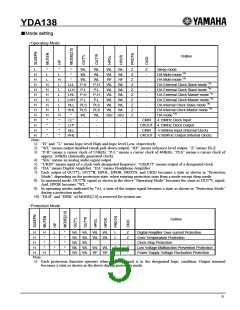
Digital Amplifier Gain Setting
VOL[1:0]
Gain
L,L
36dB
L,H
30dB
H,L
24dB
H,H
18dB
Input Sensitivity
Input Impedance
0.14V
12.1kΩ
0.28V
22.0kΩ
0.56V
37.1kΩ
1.12V
56.5kΩ
Connect a 1µF or more capacitor to the audio signal input terminal (INL and INR) for the rejection of DC signal.
And, half voltage of REFA terminal voltage (VREG) is output to the reference voltage terminals (VREFL and VREFR).
Connect a 1µF or more capacitor to the terminals for voltage stabilization.
Carrier Clock Selection Function
YDA138 can select the followings by using MODE[2:0] terminal: selection of Internal clock/External clock, selection of
Master mode/Slave mode, selection of carrier clock frequency.
MODE[2:0] setting and each operating mode
MODE[2:0]
L,L,L
Operating Mode
External Clock
Slave Mode
External Clock
Master Mode
Internal Clock
Slave Mode
Reserved
CKIO terminal
CERALOCK
Unnecessary
Carrier Clock Frequency
524kHz
466kHz
524kHz
466kHz
4.19MHz input
L,L,H
L,H,L
L,H,H
4.19MHz output
500kHz input
Necessary
H,L,L
H,L,H
H,H,L
H,H,H
Unnecessary
500kHz
500kHz
Internal Clock
Master Mode
Reserved
500kHz output
Unnecessary
When using in External Clock Mater Mode, connect a 4.19MHz resonator (CERALOCK) between XI terminal and XO
terminal. No external element to XI terminal and XO terminal is necessary, when using in Internal Clock Master Mode.
When using in multi-channel, use one YDA138 (2ch) in Master Mode and use other YDA138 in Slave Mode. At this time,
connect CKIO terminal of YDA138 used in Master Mode and that of YDA138 used in Slave Mode. In addition, select the
same clock (either Internal Clock or External Clock) in all YDA138.
In an application with AM tuner, harmonic wave of carrier clock and interference of AM carrier frequency can be prevented
by changing carrier clock frequency. The setting terminal for carrier clock frequency (MODE0) can be changed at any
timing.
The setting terminal for clock mode (MODE2, MODE1) should be changed during power-off or sleep mode (SLEEPN=L).
6

 YAMAHA [ YAMAHA CORPORATION ]