YDA138
■Mode setting
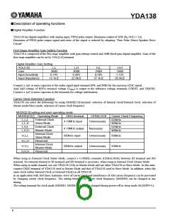
・Operating Mode
Outline
L
H
*
L
L
H
H
H
H
H
H
H
*
*
L
H
L
L
L
L
L
L
H
*
*
WL
WL
WL
P-H
P-L
P-H
P-L
WL
WL
WL
P-H
P-L
P-H
P-L
PLS
PLS
WL
-
WL
WL
RF
WL
WL
RF
Z
Z
Z
Z
Z
Z
Z
Z
Z
Z
-
Z
Sleep mode
*
-
DA Mute mode *A)
H
*
-
HA Mute mode *A)
H
LLL
LLH
LHL
LHH
WL
WL
WL
WL
WL
WL
WL
WL
WL
WL
WL
WL
-
DA External Clock Slave mode *A)
DA External Clock Slave mode *A)
DA External Clock Master mode *A)
DA External Clock Master mode *A)
DA Internal Clock Slave mode *A)
DA Internal Clock Master mode *A)
HA mode *A)
H
-
H
-
H
-
H
HLL PLS
HHL PLS
-
H
-
-
H
*
WL
SIG SIG
H
LL*
LH*
HLL
HHL
-
-
-
-
-
-
-
-
-
-
-
-
CKIN
4.19MHz Clock Input
H
*
*
-
-
CKOUT 4.19MHz Clock Output
H
*
*
-
-
CKIN
≒500kHz Input (Internal Clock)
H
*
*
-
-
CKOUT ≒500KHz Output (Internal Clock)
Note:
1) “H” and “L” means logic level High and logic level Low, respectively.
2) “WL” means output disabled (weak pull-down output). “RF” means reference level output. “Z” means Hi-Z.
3) “P-H” means a carrier clock of 524kHz. “P-L” means a carrier clock of 466kHz. “PLS” means a carrier clock of
approx. 500kHz (Internally generated clock).
4) “SIG” means an analog audio signal output.
5) “CKIN” means input of a clock with designated frequency. “CKOUT” means output of a designated clock.
6) “DA” means Digital Amplifier. “HA” means Headphone Amplifier.
7) Each output of OUT*L, OUT*R, HPOL, HPOR, PROTN, and CKIO becomes a state as shown in “Protection
Mode”, depending on the protection state, when entering protection state from a mode except sleep mode.
8) In monaural mode, OUT*R signal as shown in the above “Operating Mode” becomes the same as OUT*L signal.
And, HPOR becomes “WL.”
9) In operating modes indicated by *A), a state of the output signal becomes a state as shown in “Protection Mode”
during a protection mode.
10) “HLH” and “HHH” of MODE[2:0] is reserved for system use.
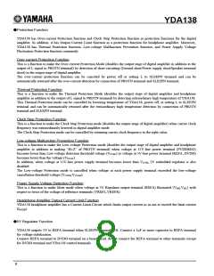
・Protection Mode
Outline
H
H
*
L
*
*
*
*
*
*
*
*
*
WL WL WL WL
WL WL WL WL
L
L
-
Z
Z
-
Digital Amplifier Over-current Protection
Over-Temperature Protection
H
H
*
WL WL
-
-
Clock Stop Protection
H
*
WL WL WL WL
WL WL RF RF
Z
-
Z
-
Low Voltage Malfunction Prevention Protection
Power Supply Voltage Fluctuation Protection
H
H
Note:
1) Each protection function operates when input terminal is in the designated logic condition. Output terminal
becomes a state as shown in the above during protection mode.
5

 YAMAHA [ YAMAHA CORPORATION ]