Virtex-6 FPGA Data Sheet: DC and Switching Characteristics
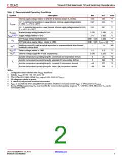
Table 2: Recommended Operating Conditions
Symbol
VCCINT
VCCAUX
Description
Min
0.95
0.87
Max
1.05
0.93
Units
Internal supply voltage relative to GND for all devices except -1L devices.
V
V
For -1L commercial temperature range devices: internal supply voltage relative
to GND, Tj = 0°C to +85°C
For -1L industrial temperature range devices: internal supply voltage relative to GND,
Tj = –40°C to +100°C
0.91
0.97
V
Auxiliary supply voltage relative to GND
Supply voltage relative to GND
2.375
1.14
2.625
2.625
2.625
V
V
(1)(2)(3)
VCCO
2.5V supply voltage relative to GND
2.5V and below supply voltage relative to GND
GND – 0.20
V
VIN
GND – 0.20 VCCO + 0.2
V
Maximum current through any pin in a powered or unpowered bank when forward
biasing the clamp diode.
–
10
mA
(5)
IIN
(6)
VBATT
Battery voltage relative to GND
1.0
2.375
0
2.5
2.625
85
V
(7)
VFS
External voltage supply for eFUSE programming
V
Junction temperature operating range for commercial (C) temperature devices
Junction temperature operating range for extended (E) temperature devices
Junction temperature operating range for industrial (I) temperature devices
Junction temperature operating range for military (M) temperature devices
°C
°C
°C
°C
0
100
100
125
Tj
–40
–55
Notes:
1. Configuration data is retained even if V
drops to 0V.
CCO
2. Includes V
of 1.2V, 1.5V, 1.8V, and 2.5V.
CCO
3. The configuration supply voltage V
4. All voltages are relative to ground.
is also known as V
.
CC_CONFIG
CCO_0
5. A total of 100 mA per bank should not be exceeded.
6. is required only when using bitstream encryption. If battery is not used, connect V
V
to either ground or V
.
BATT
BATT
CCAUX
7. During eFUSE programming, V must be within the recommended operating range and Tj = +15°C to +85°C. Otherwise, V can be
FS
FS
connected to GND.
DS152 (v3.6) March 18, 2014
www.xilinx.com
Product Specification
2

 XILINX [ XILINX, INC ]