R
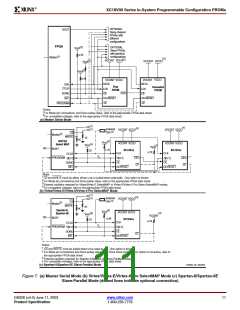
XC18V00 Series In-System Programmable Configuration PROMs
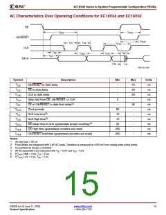
AC Characteristics Over Operating Conditions for XC18V04 and XC18V02
CE
T
T
SCE
HCE
OE/RESET
CLK
T
HOE
T
T
HC
LC
T
CYC
T
T
DF
OE
T
T
CAC
OH
T
CE
DATA
T
OH
DS026_06_012000
Symbol
Description
Min
-
Max
Units
T
T
OE/RESET to data delay
CE to data delay
10
20
20
-
ns
ns
ns
ns
ns
ns
ns
ns
ns
ns
ns
OE
CE
-
T
CLK to data delay
-
CAC
T
Data hold from CE, OE/RESET, or CLK
0
OH
(2)
T
CE or OE/RESET to data float delay
-
25
-
DF
T
Clock periods
50
10
10
25
250
250
CYC
(3)
T
CLK Low time
-
LC
HC
(3)
T
CLK High time
-
(3)
T
T
CE setup time to CLK (guarantees proper counting)
CE High time (guarantees counters are reset)
-
SCE
HCE
HOE
-
T
OE/RESET hold time (guarantees counters are reset)
-
Notes:
1. AC test load = 50 pF.
2. Float delays are measured with 5 pF AC loads. Transition is measured at 200 mV from steady state active levels.
3. Guaranteed by design, not tested.
4. All AC parameters are measured with V = 0.0V and V = 3.0V.
IL
IH
5. If T
6. If T
High < 2 µs, T = 2 µs.
HCE
HCE
CE
Low < 2 µs, T = 2 µs.
OE
DS026 (v4.0) June 11, 2003
www.xilinx.com
15
Product Specification
1-800-255-7778

 XILINX [ XILINX, INC ]