WM8983
Product Preview
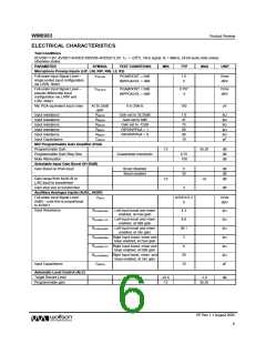
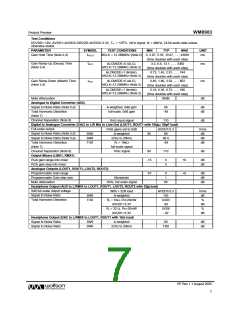
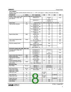
ELECTRICAL CHARACTERISTICS
Test Conditions
DCVDD=1.8V, AVDD1=AVDD2=DBVDD=AVDD2=3.3V, TA = +25oC, 1kHz signal, fs = 48kHz, 24-bit audio data unless
otherwise stated.
PARAMETER
SYMBOL
TEST CONDITIONS
MIN
TYP
MAX
UNIT
Microphone Preamp Inputs (LIP, LIN, RIP, RIN, L2, R2)
Full-scale Input Signal Level –
single ended input configuration
via L/RIN. Note1
VINFSSE
PGABOOST = 0dB
INPPGAVOL = 0dB
1.0
0
Vrms
dBV
Full-scale Input Signal Level –
pseudo differential input
configuration via L/RIP and
L/R2. Note1
VINFSPD
PGABOOST = 0dB
INPPGAVOL = 0dB
0.707
-3
Vrms
dBV
Mic PGA equivalent input noise
At 35.25dB
gain
0 to 20kHz
150
uV
Input resistance
Input resistance
Input resistance
Input resistance
Input resistance
Input Capacitance
RMICIN
RMICIN
RMICIN
RMICIP
RMICIP
CMICIN
Gain set to 35.25dB
Gain set to 0dB
1.6
47
75
90
90
10
kΩ
kΩ
kΩ
kΩ
kΩ
pF
Gain set to -12dB
RIP2INPPGA = 1
RIP2INPPGA = 0
MIC Programmable Gain Amplifier (PGA)
Programmable Gain
-12
-12
35.25
dB
dB
dB
Programmable Gain Step Size
Mute Attenuation
Guaranteed monotonic
0.75
100
Selectable Input Gain Boost (0/+20dB)
Gain Boost on PGA input
Boost disabled
Boost enabled
0
dB
dB
dB
20
Gain range from AUXL/R or
L/R2 input to boost/mixer
+6
Gain step size to boost/mixer
3
dB
Auxilliary Analogue Inputs (AUXL, AUXR)
Full-scale Input Signal Level
(0dB) – note this is proportional
to AVDD1
VINFS
AVDD1/3.3
0
Vrms
dBV
Input Resistance
RAUXINLMIN
RAUXINLTYP
RAUXINLMAX
Left Input boost and mixer
enabled, at max gain
4.3
8.6
39.1
3
kΩ
kΩ
kΩ
kΩ
kΩ
kΩ
pF
Left Input boost and mixer
enabled, at 0dB gain
Left Input boost and mixer
enabled, at min gain
RAUXINRMIN Right Input boost, mixer and
beep enabled, at max gain
RAUXINRTYP Right Input boost, mixer and
beep enabled, at 0dB gain
6
RAUXINRMAX Right Input boost, mixer and
beep enabled, at min gain
29
10
Input Capacitance
CMICIN
Automatic Level Control (ALC)
Target Record Level
-22.5
-12
-1.5
dB
Programmable gain
35.25
PP Rev 1.1 August 2005
6
w

 WOLFSON [ WOLFSON MICROELECTRONICS PLC ]