WM8959
Pre-Production
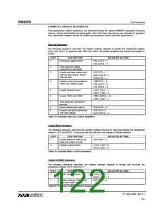
EXAMPLE CONTROL SEQUENCES
Pop-suppression control sequences are described below for typical WM8959 operations involving
start-up, muting and disabling of signal paths. Note that these descriptions are intended for guidance
only. Application software should be verified and tailored to ensure optimum performance.
Start-up Sequence
The following sequence describes the register settings required to enable the headphone outputs
LOUT and ROUT. It assumes that VMID and VREF are initially disabled and actively discharged to
AGND.
STEP
DESCRIPTION
REGISTER SETTING
1
Discharge output drivers.
DIS_LOUT = 1
DIS_ROUT = 1
2
3
Time delay for output
capacitors to discharge.
Enable soft start control and
start-up bias source. Select
start-up bias.
SOFTST = 1
BUFCOPEN = 1
POBCTRL = 1
VMIDTOG = 0
DIS_LOUT = 0
DIS_ROUT = 0
LOUT_ENA = 1
ROUT_ENA = 1
VMID_MODE = 01
VREF_ENA = 1
4
Disable active discharging of
VMID and Output drivers.
5
6
7
Enable Output drivers.
Enable VMID and VREF.
Time delay for soft-start to
execute
8
9
Select default bias source.
POBCTRL = 0
SOFTST = 0
Disable soft start control and
soft start voltage.
BUFCOPEN = 0
Table 78 Example Start-Up Control Sequence
Output Mute Sequence
The following sequence describes the register settings required to mute and disable the headphone
outputs LOUT and ROUT. It assumes that the soft start bias voltage is initially disabled.
STEP
DESCRIPTION
REGISTER SETTING
1
Enable buffered VMID at all
input and output circuits.
BUFIOEN = 1
2
Disable output drivers
LOUT_ENA = 0
ROUT_ENA = 0
Table 79 Example Mute Control Sequence
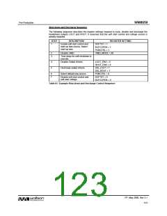
Output Un-Mute Sequence
The following sequence describes the register settings required to enable and un-mute the
headphone outputs LOUT and ROUT.
STEP
DESCRIPTION
REGISTER SETTING
LOUT_ENA = 1
1
Enable Output drivers.
ROUT_ENA = 1
BUFIOEN = 0
2
Disable buffered VMID at all
input and output circuits.
Table 80 Example Un-Mute Control Sequence
PP, May 2008, Rev 3.1
122
w

 WOLFSON [ WOLFSON MICROELECTRONICS PLC ]