PDF
最近搜索
热门搜索
发布采购

| 型号: | WM8945 |
| PDF下载: | 下载PDF文件 查看货源 |
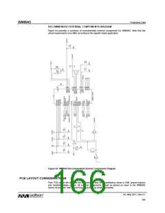
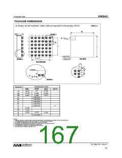
| 内容描述: | 单声道低功耗编解码器与视频缓冲器和触摸屏控制器 [Mono Low-Power CODEC with Video Buffer and Touch Panel Controller] |
| 分类和应用: | 解码器编解码器控制器 |
| 文件页数/大小: | 169 页 / 1604 K |
| 品牌: |  WOLFSON [ WOLFSON MICROELECTRONICS PLC ] WOLFSON [ WOLFSON MICROELECTRONICS PLC ] |
专业IC领域供求交易平台:提供全面的IC Datasheet资料和资讯,Datasheet 1000万数据,IC品牌1000多家。