WM8945
Production Data
Due to the wide tolerance of many types of ceramic capacitors, care must be taken to ensure that the
selected components provide the required capacitance across the required temperature and voltage
ranges in the intended application. For most application the use of ceramic capacitors with capacitor
dielectric X5R is recommended.
MICROPHONE BIAS CIRCUIT
The WM8945 is designed to interface easily with electret microphones. These may be connected in
single-ended or differential configurations. The single-ended method allows greater capability for the
connection of multiple audio sources simultaneously, whilst the differential method provides better
performance due to its rejection of common-mode noise.
In either configuration, the microphone requires a bias current (electret condenser microphones) or
voltage supply (silicon microphones), which can be provided by MICBIAS. This reference is
generated by an output-compensated amplifier, which requires an external capacitor in order to
guarantee accuracy and stability. The recommended capacitance is 4.7F, although it may be
possible to reduce this to 1F if the analogue supply (LDOVOUT) is not too noisy. A ceramic type is a
suitable choice here, providing that care is taken to choose a component that exhibits this
capacitance at the intended MICBIAS voltage.
Note that the MICBIAS voltage may be adjusted using register control to suit the requirements of the
microphone. Also note the WM8945 supports a maximum current of 3mA. If more than one
microphone is connected to the MICBIAS, then combined current must not exceed 3mA.
A current-limiting resistor is also required when using an electret condenser microphone (ECM). The
resistance should be chosen according to the minimum operating impedance of the microphone and
MICBIAS voltage so that the maximum bias current of the WM8945 is not exceeded. Wolfson
recommends a 2.2k current limiting resistor as it provides compatibility with a wide range of
microphone models.
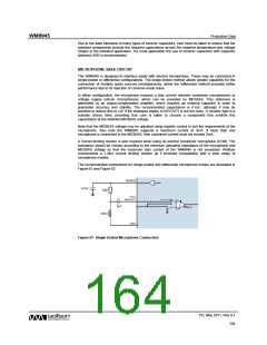
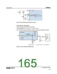
The recommended connections for single-ended and differential microphone modes are illustrated in
Figure 61 and Figure 62.
Figure 61 Single-Ended Microphone Connection
PD, May 2011, Rev 4.1
164
w

 WOLFSON [ WOLFSON MICROELECTRONICS PLC ]