WM8904
Pre-Production
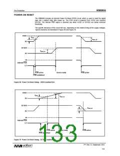
The P¯O¯¯R signal is undefined until AVDD has exceeded the minimum threshold, Vpora Once this
threshold has been exceeded, P¯O¯¯R is asserted low and the chip is held in reset. In this condition, all
writes to the control interface are ignored. Once AVDD and DCVDD have reached their respective
power on thresholds, P¯O¯¯R is released high, all registers are in their default state, and writes to the
control interface may take place.
Note that a minimum power-on reset period, TPOR, applies even if AVDD and DCVDD have zero rise
time. (This specification is guaranteed by design rather than test.)
On power down, P¯O¯¯R is asserted low when any of AVDD or DCVDD falls below their respective
power-down thresholds.
Typical Power-On Reset parameters for the WM8904 are defined in Table 90.
SYMBOL
Vpora
DESCRIPTION
AVDD threshold below which POR is undefined
Power-On threshold (AVDD)
TYP
0.25
1.15
1.12
0.57
0.55
9.5
UNIT
V
Vpora_on
Vpora_off
Vpord_on
Vpord_off
TPOR
V
Power-Off threshold (AVDD)
V
Power-On threshold (DCVDD)
Power-Off threshold (DCVDD)
Minimum Power-On Reset period
V
V
s
Table 90 Typical Power-On Reset parameters
Notes:
1. If AVDD and DCVDD suffer a brown-out (i.e. drop below the minimum recommended operating
level but do not go below Vpora_off or Vpord_off) then the chip does not reset and resumes normal
operation when the voltage is back to the recommended level again.
2. The chip enters reset at power down when AVDD or DCVDD falls below Vpora_off or Vpord_off. This
may be important if the supply is turned on and off frequently by a power management system.
3. The minimum Tpor period is maintained even if DCVDD and AVDD have zero rise time. This
specification is guaranteed by design rather than test.
PP, Rev 3.3, September 2012
134
w

 WOLFSON [ WOLFSON MICROELECTRONICS PLC ]