WM8774
Product Preview
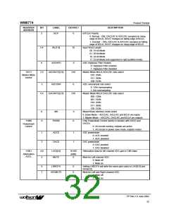
REGISTER
ADDRESS
BIT
LABEL
DEFAULT
DESCRIPTION
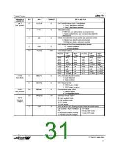
3
BCP
0
BITCLK Polarity
0: Normal - DIN, DACLRC & ADCLRC sampled on rising
edge of BCLK; DOUT changes on falling edge of BCLK.
1: Inverted - DIN, DACLRC & ADCLRC sampled on falling
edge of BCLK; DOUT changes on rising edge of BCLK.
5:4
WL[1:0]
10
Input Word Length
00: 16-bit Mode
01: 20-bit Mode
10: 24-bit Mode
11: 32-bit Mode (not supported in right justified mode)
ADC Highpass Filter Disable:
0: Highpass Filter enabled
1: Highpass Filter disabled
Master Mode MCLK:ADCLRC ratio select:
010: 256fs
8
ADCHPD
0
10111
2:0
ADCRATE[2:0]
010
Master Mode
control
011: 384fs
100: 512fs
3
ADCOSR
0
ADC oversample rate select
0: 128x oversampling
1: 64x oversampling
6:4
DACRATE[2:0]
010
Master Mode MCLK:DACLRC ratio select:
000: 128fs
001: 192fs
010: 256fs
011: 384fs
100: 512fs
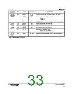
8
0
MS
0
0
Maser/Slave interface mode select
0: Slave Mode – ADCLRC, DACLRC and BCLK are inputs
1: Master Mode – ADCLRC, DACLRC and BCLK are outputs
11000
PWDN
Chip Powerdown Control (works in tandem with ADCD and
DACD):
Powerdown
Control
0: All circuits running, outputs are active
1: All circuits in power save mode, outputs muted
ADC powerdown:
1
2
ADCD
DACD
1
1
0: ADC enabled
1: ADC disabled
DAC powerdown
0: DAC enabled
1: DAC disabled
11001
4:0
5
LAG[4:0]
MUTE
01100
(0dB)
0
Attenuation data for left channel ADC gain in 1dB steps
Attenuation
ADCL
Mute for Left channel ADC:
0: Mute off
1: Mute on
6
7
LRBOTH
0
0
Setting LRBOTH will write the same gain value to LAG[4:0] and
RAG[4:0]
ADCMUTE
Mute for Left and Right channel ADC:
0: Mute off
1: Mute on
PP Rev 1.0 June 2002
32
ꢀꢀ

 WOLFSON [ WOLFSON MICROELECTRONICS PLC ]