WM8352
Production Data
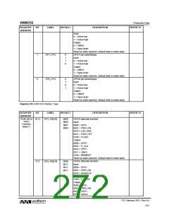
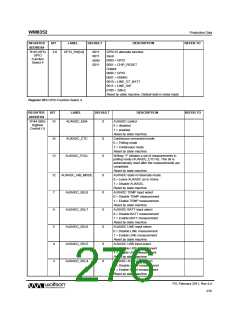
REGISTER
ADDRESS
BIT
LABEL
DEFAULT
DESCRIPTION
GPIO12 alternate function:
REFER TO
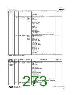
R143 (8Fh)
GPIO
Function
Select 4
3:0
GP12_FN[3:0]
0011
0011
0000
0011
Input:
0000 = GPIO
0001 = CHIP_RESET
Output:
0000 = GPIO
0001 = ISINKE
0010 = LINE_GT_BATT
0011 = LINE_SW
0100 = 32kHz
Reset by state machine. Default held in metal mask.
Register 8Fh GPIO Function Select 4
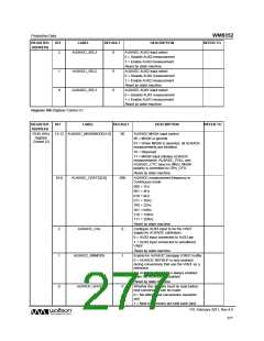
REGISTER
ADDRESS
BIT
LABEL
DEFAULT
DESCRIPTION
REFER TO
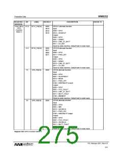
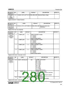
R144 (90h)
Digitiser
Control (1)
15
AUXADC_ENA
0
0
0
AUXADC control
0 = disabled
1 = enabled
Reset by state machine.
Continuous conversion mode:
0 = Polling mode
14
13
AUXADC_CTC
AUXADC_POLL
1 = Continuous mode
Reset by state machine.
Writing “1” initiates a set of measurements in
polling mode (AUXADC_CTC=0). This bit is
automatically reset after the measurements are
completed.
Reset by state machine.
12
7
AUXADC_HIB_MODE
AUXADC_SEL8
AUXADC_SEL7
AUXADC_SEL6
AUXADC_SEL5
AUXADC_SEL4
0
0
0
0
0
0
AUXADC state in hibernate mode:
0 = Leave AUXADC as in Active
1 = Disable AUXADC.
Reset by state machine.
AUXADC TEMP input select
0 = Disable TEMP measurement
1 = Enable TEMP measurement
Reset by state machine.
6
AUXADC BATT input select
0 = Disable BATT measurement
1 = Enable BATT measurement
Reset by state machine.
5
AUXADC LINE input select
0 = Disable LINE measurement
1 = Enable LINE measurement
Reset by state machine.
4
AUXADC USB input select
0 = Disable USB measurement
1 = Enable USB measurement
Reset by state machine.
3
AUXADC AUX4 input select
0 = Disable AUX4 measurement
1 = Enable AUX4 measurement
Reset by state machine.
PD, February 2011, Rev 4.4
276
w

 WOLFSON [ WOLFSON MICROELECTRONICS PLC ]