Production Data
WM8352
17.7 BATTERY CHARGER
17.7.1 GENERAL DESCRIPTION
The WM8352 incorporates a battery charger which is designed for single-cell lithium batteries. The
battery charger can operate from either the Wall (LINE) or USB power sources. Trickle charging at
50mA is enabled by default. The battery charger configuration and termination can run without any
intervention required by the host processor.
The battery charger voltage and currents are programmable. Trickle charging at either 50mA or
100mA is supported; fast charging from 50mA up to 750mA is possible under certain conditions.
Note that charging from the USB power is subject to the 100mA or 500mA overall limit on the USB
source (see Section 17.4).
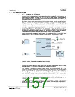
Battery pack temperature sensing is enabled by default. The connection to the battery’s NTC resistor
is made using the SWVRTC pin and the AUX1 pin, as illustrated in Figure 76. The SWVRTC pin is a
reference source controlled by the WM8352. The AUX1 pin (also an input to the AUXADC) is used as
the input to the temperature sensing circuit. Note that the absence of the NTC connection will lead to
a temperature failure condition being detected and battery charging will not be possible.
Typical connections for the WM8352 battery charger are illustrated in Figure 76. The resistor value
between SWVRTC and AUX1 should be selected to match the NTC. A typical value is 100kΩ.
Figure 76 Typical Connections for WM8352 Battery Charger
The WM8352 monitors the battery status via the AUX1 pin and by voltage/current sensing on other
pins. See Section 17.7.7 for details of the battery fault conditions and reporting.
If the application is intended to run without a battery present, then it is recommended that a 3.3μF
capacitor be placed on the BATT pin to ensure correct charger behaviour. In this case, the Battery
Charger interrupts should also be masked, as these will be invalid - see Section 17.7.8 for details of
the Battery Charger Interrupts. It is recommended that the Battery Charger also be disabled in this
case - note that the Battery Charger is enabled by default, including on entry to the OFF power state.
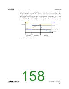
A typical battery charge cycle is illustrated in Figure 77. This shows both the trickle charge and fast
charge processes.
The trickle charge mode is a constant current mode. Trickle charging is enabled when the battery
voltage falls below a charging threshold voltage; it is disabled when the charge current falls to a
programmable ‘End of Charge’ threshold level.
PD, February 2011, Rev 4.4
157
w

 WOLFSON [ WOLFSON MICROELECTRONICS PLC ]