WM8352
Production Data
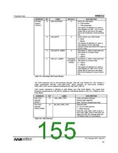
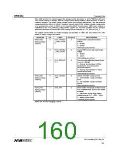
17.5 EXTERNAL INTERRUPTS
The power supply control circuit has a first-level interrupt, EXT_INT (see Section 24). This comprises
three second-level interrupts which indicate if the USB, Wall or Battery supplies have been
connected or disconnected. Internal feedback signals USB_FB, WALL_FB and BATT_FB are used
to indicate when the associated supplies are present. Note that these interrupt events occur on both
the rising and falling edges of the trigger events. They can be masked by setting the applicable mask
bits as defined in Table 103.
ADDRESS
BIT
LABEL
DESCRIPTION
R31 (1Fh)
15
EXT_USB_FB_EINT
USB_FB changed interrupt.
Comparator
Interrupt Status
(Rising and Falling Edge triggered)
Note: This bit is cleared once read.
WALL_FB changed interrupt.
14
13
EXT_WALL_FB_EINT
EXT_BATT_FB_EINT
(Rising and Falling Edge triggered)
Note: This bit is cleared once read.
BATT_FB changed interrupt.
(Rising and Falling Edge triggered)
Note: This bit is cleared once read.
R39 (27h)
15:13
“IM_” + name of respective bit Interrupt mask.
in R31
Comparator
Interrupt Status
Mask
0 = Do not mask interrupt.
1 = Mask interrupt.
Each bit in R39 enables or masks the
corresponding bit in R31. The default
value for these bits is 0 (unmasked).
Table 103 External Interrupts
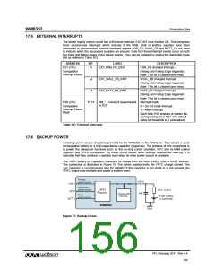
17.6 BACKUP POWER
A backup power source should be provided for the WM8352 on the VRTC pin. This can be a small
rechargeable battery or a high-capacitance capacitor (supercap). The purpose of this component is
to power the always-on functions such as the on-chip crystal oscillator, RTC and ALARM control
registers and UVLO comparator. As these circuit blocks store settings required for start-up, it is
desirable that they continue to operate even when no other power source is available.
The VRTC battery (or capacitor) maintains its charge from the Wall (LINE), USB or BATT sources.
The connection is illustrated in Figure 75. The series resistor limits the VRTC charge current. The
1μF capacitor is recommended also for stability; if this capacitor is too small or is not present, the
VRTC output may oscillate and cause a system reset.
Figure 75 Backup Power
PD, February 2011, Rev 4.4
156
w

 WOLFSON [ WOLFSON MICROELECTRONICS PLC ]