Production Data
WM8352
ADDRESS
BIT
LABEL
DEFAULT
DESCRIPTION
Opens the USB switch
R4 (04h)
14
USB_SUSPEND
0
System
0 = USB enabled
Control 2
1 = USB suspended
The register bit defaults to 0, when a
reset happens or LINE < UVLO or the
system fail on boot due to the upper
limit of the Hysteresis Comp not being
met.
13
USB_MSTR
0
Set the chip to be a USB master
0 = Slave
1 = Master
The register bit defaults to 0, when a
reset happens or the USB state
machine moves from MASTER mode to
SLAVE mode.
11
9
USB_MSTR_500MA
USB_SLV_500MA
0
Set 500mA or 100mA mode when the
USB switch is in master mode
0 = 100mA
1 = 500mA
Dependant
Set 500mA or 100mA mode when the
on CONFIG USB switch is in slave mode
settings
0 = 100mA
1 = 500mA
The register bit defaults to 0, when a
reset happens or LINE<UVLO or the
system fail on boot due to the upper
limit of the Hysteresis Comp not been
met.
Table 101 Selecting USB Power Modes
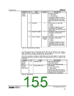
The USB connection has its own first-level interrupt, USB_INT (see Section 24). This contains a
single second-level interrupt, USB_LIMIT_EINT, which indicates an over-current condition.
USB_LIMIT_EINT can be masked by setting the IM_USB_LIMIT_EINT bit.
USB Current monitoring is effective in USB Master and USB Slave Modes. The current limit
threshold is determined by USB_MSTR_500MA (in USB Master Mode) or USB_SLV_500MA (in USB
Slave Mode).
ADDRESS
BIT
LABEL
DESCRIPTION
USB Limit Switch interrupt.
(Rising Edge triggered)
Note: This bit is cleared once read.
Interrupt mask.
R26 (1Ah)
10
USB_LIMIT_EINT
Interrupt
Status 2
R34 (22h)
10
IM_USB_LIMIT_EINT
Interrupt
Status 2 Mask
0 = Do not mask interrupt.
1 = Mask interrupt.
When IM_USB_LIMIT_EINT is set to 1,
then USB_LIMIT_EINT in R26 does not
trigger an USB_INT interrupt when set.
The default value is 0 (unmasked).
Table 102 USB Interrupt
PD, February 2011, Rev 4.4
155
w

 WOLFSON [ WOLFSON MICROELECTRONICS PLC ]