I5216 SERIES
Advanced Information
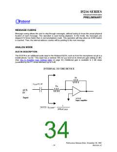
PRELIMINARY
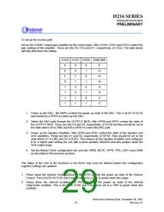
3. Power down the AUX IN amplifier—Bit AXPD controls the power up state of the AUX IN input
amplifier. This is bit D10 of CFG0 and it should be set to a ONE to power down this stage.
4. Power down the SUM1 and SUM2 Mixer amplifiers—Bits S1M0 and S1M1 control the SUM1 mixer
and bits S2M0 and S2M1 control the SUM2 mixer. These are bits D7 and D8 in CFG1, and bits D5
and D6 in CFG1, respectively. All four bits should be set to a ONE in order to power down these
two amplifiers.
5. Power down the FILTER stage—Bit FLPD controls the power up state of the FILTER stage in the
device. This is bit D1 in CFG1 and should be set to a ONE to power down the stage.
6. Power down the AGC amplifier—Bit AGPD controls the power up state of the AGC amplifier. This
is bit D0 in CFG1 and should be set to a ONE to power down this stage.
7. Don’t Care bits—All other bits are not used in Feed Through Mode. Their bits may be set to either
level. In this example, we will set all the "Don’t Care" bits to a ZERO.
The following example shows the setup for a full-duplex feed-through path at 8 kHz sampling rate. The
twos complement data format is enabled. The High Pass filter is also enabled. The Master Clock input
is running at 13.824MHz.
CFG0=0010 0101 0100 1011 (hex 254B)
and
CFG1=0000 0001 1110 0011 (hex 01E3).
and
CFG2=0000 0000 0100 0000 (hex 0040).
Since three registers are being loaded, CFG0 is loaded, followed by the loading of CFG1 and CFG2.
These three registers must be loaded in this order. The internal set up for these registers will take
effect synchronously, with the rising edge of SCL.
CALL RECORD
The call record mode adds the ability to record the incoming phone call. In most applications, the I5216
would first be set up for Feed Through Mode as described above. When the user wishes to record the
incoming call, the set up of the chip is modified to add that ability. For the purpose of this
explanation, we will use the 6.4 kHz ChipCorder sample rate during recording.
The block diagram of the I5216 shows that the Multilevel Storage array is always driven from the
SUM2 SUMMING amplifier. The path traces back from there, through the LOW PASS Filter, the
FILTER MUX, the SUM1 SUMMING amplifier, the SUM1 MUX, back to the origin CODEC. Feed
Through Mode has already powered up the CODEC, so we only need to power up and enable the path
to the Multilevel Storage array from that point:
Publication Release Date: November 30, 2001
- 30
Revision A1

 WINBOND [ WINBOND ]