I5216 SERIES
Advanced Information
PRELIMINARY
To set up the receive path:
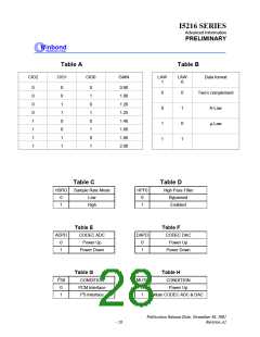
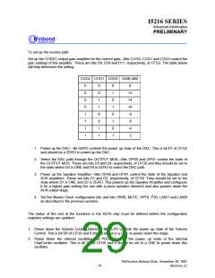
Set up the CODEC output gain amplifier for the correct gain—Bits COG0, COG1 and COG2 control the
gain settings of this amplifier. These are bits D9, D10 and D11, respectively, of CFG2. The table below
will help determine the setting
COG2 COG1 COG0 GAIN (dB)
0
0
0
0
1
1
1
1
0
0
1
1
0
0
1
1
0
1
0
1
0
1
0
1
0
+2
+4
+6
-8
-6
-4
-2
1. Power up the DAC—Bit DAPD controls the power up state of the DAC. This is bit D1 of CFG2
and should be a ZERO to power up the DAC.
2. Select the DAC path through the OUTPUT MUX—Bits OPS0 and OPS1 control the state of
the OUTPUT MUX. These are bits D3 and D4, respectively, of CFG0 and they should be set to
the state where D3 is ONE and D4 is ZERO to select the DAC path.
3. Power up the Speaker Amplifier—Bits OPA0 and OPA1 control the state of the Speaker and
AUX amplifiers. These are bits D1 and D2, respectively, of CFG0. They should be set to the
state where D1 is ONE and D2 is ZERO. This powers up the Speaker Amplifier and configures
it for a higher gain setting (for use with a piezo speaker element) and also powers down the
AUX output stage.
4. Set the Master Clock configuration bits and bits HSR0, MUTE, HPF0, I2S0, LAW1 and LAW0
as described in the previous sections.
The status of the rest of the functions in the I5216 chip must be defined before the configuration
registers settings are updated:
1. Power down the Volume Control Element—Bit VLPD controls the power up state of the Volume
Control. This is bit D0 of CFG0 and it should be set to a ONE to power down this stage.
2. Power down the internal oscillator—Bit PDOS controls the power up state of the internal
ChipCorder oscillator. This is bit D8 of CFG0 and it should be set to a ONE to power down this
oscillator
Publication Release Date: November 30, 2001
- 29
Revision A1

 WINBOND [ WINBOND ]