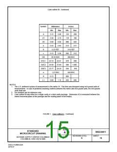
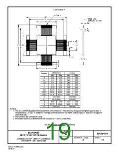
Case outline Y.
Millimeters
Inches
Min
Symbol
Min
Max
3.56
Max
.140
A
A1
A2
b
2.92
1.14
.115
.045
1.91
.075
1.14
1.39
.045
.055
0.31
0.46
.012
.018
c
0.23
0.31
.009
.012
D/E
D1/E1
D2/E2
e
63.63
39.24
73.28
66.42
40.01
84.20
2.505
1.545
2.885
2.615
1.575
3.315
1.27 BSC
20.32 BSC
.050 BSC
.800 BSC
e1
j
4.83
37.72
5.33
.190
1.485
.210
k
38.48
1.515
S1
9.65 BSC
.380 BSC
NOTES:
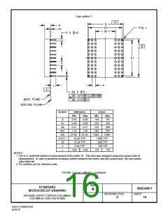
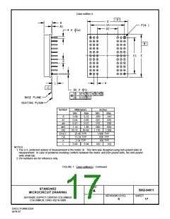
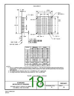
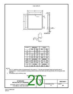
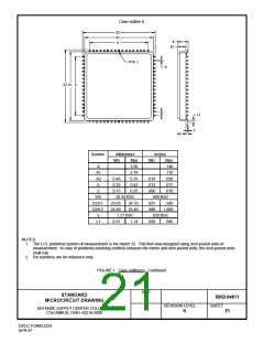
1. The U.S. preferred system of measurement is the metric SI. This item was designed using inch-pound units of
measurement. In case of problems involving conflicts between the metric and inch-pound units, the inch-pound
units shall rule.
2. Pin numbers are for reference only.
3. For solder lead finish, dimension b will increase by +.003" (+0.008 mm).
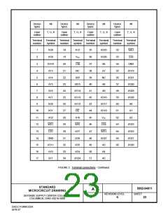
FIGURE 1. Case outline(s) - Continued.
SIZE
STANDARD
MICROCIRCUIT DRAWING
5962-94611
A
REVISION LEVEL
SHEET
DEFENSE SUPPLY CENTER COLUMBUS
COLUMBUS, OHIO 43216-5000
19
R
DSCC FORM 2234
APR 97

 WEDC [ WHITE ELECTRONIC DESIGNS CORPORATION ]