6N137 / VO2601 / 11 / VO2630 / 31 / VO4661
Vishay Semiconductors
120
100
80
60
40
20
0
300
t
4 kΩ
PLH,
t , R = 4 kΩ
r
L
250
200
150
100
50
t
1 kΩ
PLH,
t
350 Ω
PLH,
t , R = 350 Ω
f
L
t , R = 1 kΩ
f
L
t , R = 4 kΩ
t
350 Ω
f
L
PHL,
t , R = 1 kΩ
r
L
t
1 kΩ
PHL,
t
4 kΩ
PHL,
t , R = 350 Ω
r
L
0
5
7
9
11
13
15
–40 –20
T
0
20
40
60
80 100
17623
I
– Forward Current ( mA )
17626
– Ambient Temperature ( °C )
amb
F
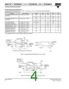
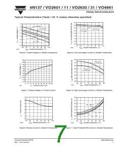
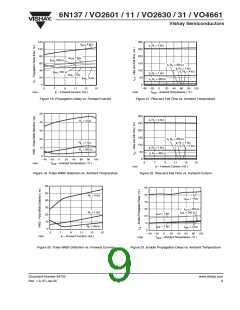
Figure 18. Propagation Delay vs. Forward Current
Figure 21. Rise and Fall Time vs. Ambient Temperature
50
300
t , R = 4 kΩ
r
L
R
= 4 kΩ
L
40
30
20
10
0
250
200
150
100
50
t , R = 350 Ω
f
L
R
L
= 1 kΩ
t , R = 1 kΩ
f
L
t , R = 4 kΩ
f
L
t , R = 1 kΩ
r
L
R
L
= 350 Ω
t , R = 350 Ω
r
L
0
–40 –20
0
20
40
60
80 100
5
7
9
11
13
15
17624
T
amb
– Ambient Temperature ( °C )
17627
I – Forward Current ( mA )
F
Figure 19. Pulse Width Distortion vs. Ambient Temperature
Figure 22. Rise and Fall Time vs. Forward Current
60
50
60
50
R
R
= 4 kΩ
= 1 kΩ
L
t
= 4 kΩ
eLH
40
30
20
10
0
40
30
20
10
0
t
= 350 Ω
eLH
t
= 350 Ω
L
eHL
t
= 1 kΩ
eLH
R
L
= 350 Ω
t
= 1 kΩ
eHL
t
= 4 kΩ
eHL
5
7
9
11
13
15
–40 –20
T
0
20
40
60
80 100
17625
I – Forward Current ( mA )
F
17628
– Ambient Temperature ( °C )
amb
Figure 20. Pulse Width Distortion vs. Forward Current
Figure 23. Enable Propagation Delay vs. Ambient Temperature
Document Number 84732
Rev. 1.0, 07-Jun-05
www.vishay.com
9

 VISHAY [ VISHAY ]