10-FU073AA030SM-PF04H06
datasheet
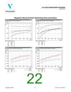
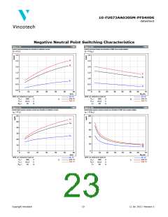
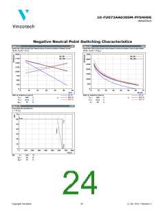
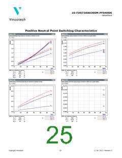
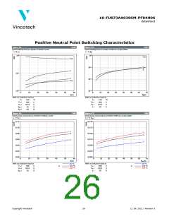
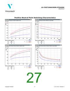
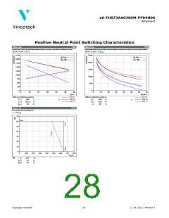
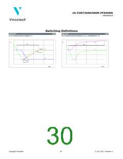
Positive Neutral Point Switching Characteristics
figure 44.
IGBT
figure 45.
IGBT
Typical switching times as a function of collector current
Typical switching times as a function of IGBT turn on gate resistor
t = f(IC)
t = f(Rg)
0
10
0
10
td(off)
td(off)
td(on)
-1
10
tf
tr
tf
-1
10
tr
-2
10
td(on)
-2
10
-3
10
0
10
20
30
40
50
60
IC(A)
0
10
20
30
40
50
60
70
Rg(Ω)
With an inductive load at
With an inductive load at
Tj =
Tj =
150
400
0/15
16
°C
V
150
400
0/15
30
°C
VCE
=
=
=
=
VCE
=
=
=
V
V
A
VGE
Rgon
Rgoff
VGE
IC
V
Ω
Ω
64
figure 46.
FWD
figure 47.
FWD
Typical reverse recovery time as a function of collector current
Typical reverse recovery time as a function of IGBT turn on gate resistor
trr = f(IC)
trr = f(Rgon)
0,12
0,10
0,08
0,06
0,04
0,02
0,00
0,150
0,125
0,100
0,075
0,050
0,025
0,000
trr
trr
trr
trr
trr
trr
0
10
20
30
40
50
60
0
10
20
30
40
50
60
70
IC(A)
Rgon(Ω)
With an inductive load at
With an inductive load at
25 °C
25 °C
VCE
VGE
Rgon
=
=
=
VCE
VGE
IC
=
=
=
400
0/15
16
V
V
Ω
125 °C
150 °C
400
0/15
30
V
V
A
125 °C
150 °C
Tj:
Tj:
Copyright Vincotech
26
11 Jul. 2022 / Revision 1

 VINCOTECH [ VINCOTECH ]