SO-502 SAW Based Oscillator
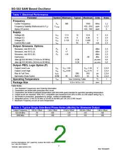
Table 1. Electrical Performance
Parameter
Symbol Minimum Typical Maximum Units
Notes
Frequency
Center Frequency
FN
FSTAB
300
1350
+50, -250
+50, -100
MHz
ppm
ppm
1,2
1,2,7
5
Frequency Stability (Referenced to FO)
Aging (10 years)
Supply
Voltage (B)
Voltage (C)
Voltage (D)
Current (No Load)
VCC
VCC
VCC
ICC
11.4
4.75
3.135
12
5
3.3
55
12.6
5.25
3.450
70
V
V
2,3
2,3
2,3
2,3
V
mA
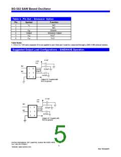
Output- Sinewave Options
Sinewave, into 50 Ώ (G)
PO
PO
PO
0
dBm
dBm
2,3
2,3
2,3
2,3
5,6
5,6
Sinewave, into 50 Ώ (J)
+7
Sinewave, into 50 Ώ (K)
+10
dBm
Harmonics
-20
dBc
ps,rms
ps,rms
Jitter @ 622.08 MHz (12 kHz to 20 MHz)
Jitter @ 622.08 MHz (50 kHz to 80 MHz)
0.28
0.29
Output- PECL Logic Option (F)
Output Level Low
VOL
VOL
tR,tF
SYM
VCC-1.95
VCC-0.98
VCC-1.63
VCC-0.75
350
V
V
ps
%
2,3,4
2,3,4
2,3,4
2,3,4
Output Level High
Rise & Fall Time
200
49/51
Symmetry (Duty Cycle)
45
55
TOP
See Ordering Table
9.0 x 14.0 x 4.5
ºC
mm
1
Operating Temperature
Package Size
Table Notes:
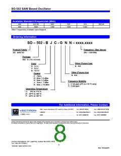
1. See Standard Frequencies and Ordering Information
2. Parameters are tested with production test circuit
3. Parameters are tested at ambient temperature with test limits guard-banded for specified operating temperature.
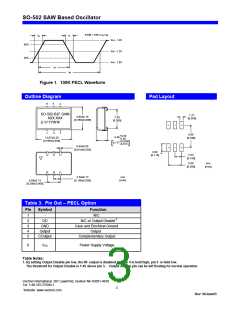
4. Output levels are standard 100K PECL compatible and measured from 20% to 80% of a full output swing (Fig 1).
5. Not tested in production, guaranteed by design, verified at qualification.
6. Integrated across 12 kHz to 20 MHz or 50 kHz to 80 MHz per GR-253-CORE Issue3.
7. Maximum Frequency occurs at room temperature
Table 2. Typical Single Side-Band Phase Noise (dBc/Hz) for Sinewave Output
Output Frequency
622.08 MHz
100 Hz Offset
1 kHz Offset
-100
10 kHz Offset
-125
100 kHz Offset
-155
1 MHz Offset
-160
-70
-70
1000 MHz
-100
-125
-155
-160
Vectron International, 267 Lowell Rd, Hudson NH 03051-4916
Tel: 1-88-VECTRON-1
Website: www.vectron.com
2
Rev: 06June05

 VECTRON [ Vectron International, Inc ]