TMC5160 DATASHEET (Rev. 1.08 / 2018-NOV-19)
116
24 Standalone Operation
For standalone operation, no SPI interface is required to configure the TMC5160. All pins with suffix
CFG0 to CFG6 have a special meaning in this mode and can bei tied either to VCC_IO or to GND.
+VM
Optional use lower
voltage down to 12V
22n
100V
100n
16V
100n
CE
+VM
VSA
12VOUT
5VOUT
CB2
CB
CB
HB2
CB1
470n
charge pump
HS
HS
11.5V Voltage
regulator
Step&Dir input
with microPlyer
100n
2.2µ
2.2µ
5V Voltage
regulator
HB1
BMB1
RG
RG
2R2
VCC
BMB2
LB1
470n
TMC5160
LS
LS
RG
RG
CFG0
CFG1
CFG2
CFG3
CFG4
CFG5
CFG6
Microstep Resolution
8 / 16 / 32 / 64
LB2
SRBH
47R
47R
Configuration
interface
(GND or VCC_IO
level)
Run Current Setting
16 / 18 / 20 / 22 /
24 / 26 / 28 / 31
RS
N
stepper
motor
SRBL
S
Controller
Chopper
+VM
CB
CA2
spreadCycle (GND) /
stealthChop (VCC_IO)
Current Reduction
Enable (VCC_IO)
B.Dwersteg, ©
TRINAMIC 2014
HA2
CA1
B.Dwersteg, ©
TRINAMIC 2014
470n
HS
HS
CB
RG
DIAG1
DIAG0
HA1
BMA1
Index pulse
Driver error
RG
Status out
(open drain)
opt. ext. clock
12-16MHz
BMA2
LA1
CLK_IN
LS
LS
Keep inductivity of the fat
interconnections as small
as possible to avoid
RG
RG
+VIO
3.3V or 5V
I/O voltage
VCC_IO
LA2
undershoot of BM <-5V!
SRAH
100n
47R
47R
Use low inductivity SMD
type, e.g. 1210 or 2512
mode selection
RS
SRAL
resistor for RS
!
pd
Bootstrap capacitors CB
:
220nF for MOSFETs with QG<20nC, 470nF for larger QG
Slope control resistors RG: Adapt to MOSFET to yield slopes of roughly
100ns. Slope must be slower than bulk diode recovery time.
+VIO
Standalone mode
opt. driver enable
Figure 24.1 Standalone operation with TMC5160 (pins shown with their standalone mode names)
To activate standalone mode, tie pin SPI_MODE to GND and pin SD_MODE high. In this mode, the
driver acts as a pure STEP and DIR driver. SPI and single wire are off. The driver works in spreadCycle
mode or stealthChop mode. With regard to the register set, the following settings are activated:
GCONF settings:
GCONF.diag0_error = 1: DIAG0 works in open drain mode and signals driver error.
GCONF.diag1_index = 1: DIAG1 works in open drain mode and signals microstep table index position.
The following settings are affected by the CFG pins in order to ensure correct configuration:
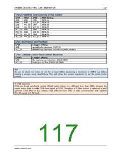
CFG0/CFG1: CONFIGURATION OF MICROSTEP RESOLUTION FOR STEP INPUT
CFG1
GND
GND
CFG0
GND
Microstep Setting
8 microsteps, MRES=5
VCC_IO 16 microsteps, MRES=4
32 microsteps, MRES=3
VCC_IO GND
VCC_IO VCC_IO 64 microsteps, MRES=2
www.trinamic.com

 TRINAMIC [ TRINAMIC MOTION CONTROL GMBH & CO. KG. ]