TMC5160 DATASHEET (Rev. 1.08 / 2018-NOV-19)
115
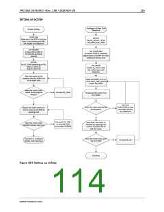
23 Getting Started
Please refer to the TMC5160 evaluation board to allow a quick start with the device, and in order to
allow interactive tuning of the device setup in your application. Chapter 22 will guide you through the
process of correctly setting up all registers.
23.1 Initialization Examples
SPI datagram example sequence to enable the driver for step and direction operation and initialize
the chopper for spreadCycle operation and for stealthChop at <30 RPM @ 12MHz clock:
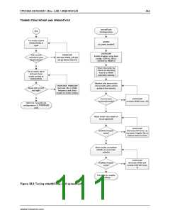
SPI send: 0xEC000100C3; // CHOPCONF: TOFF=3, HSTRT=4, HEND=1, TBL=2, CHM=0 (spreadCycle)
SPI send: 0x9000061F0A; // IHOLD_IRUN: IHOLD=10, IRUN=31 (max. current), IHOLDDELAY=6
SPI send: 0x910000000A; // TPOWERDOWN=10: Delay before power down in stand still
SPI send: 0x8000000004; // EN_PWM_MODE=1 enables stealthChop (with default PWM_CONF)
SPI send: 0x93000001F4; // TPWM_THRS=500 yields a switching velocity about 35000 = ca. 30RPM
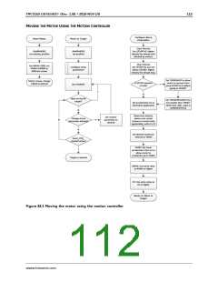
SPI sample sequence to enable and initialize the motion controller and move one rotation (51200
microsteps) using the ramp generator. A read access querying the actual position is also shown.
SPI send: 0xA4000003E8; // A1
SPI send: 0xA50000C350; // V1
SPI send: 0xA6000001F4; // AMAX
SPI send: 0xA700030D40; // VMAX
SPI send: 0xA8000002BC; // DMAX
SPI send: 0xAA00000578; // D1
= 1 000 First acceleration
= 50 000 Acceleration threshold velocity V1
= 500 Acceleration above V1
= 200 000
= 700 Deceleration above V1
= 1400 Deceleration below V1
SPI send: 0xAB0000000A; // VSTOP = 10 Stop velocity (Near to zero)
SPI send: 0xA000000000; // RAMPMODE = 0 (Target position move)
// Ready to move!
SPI send: 0xADFFFF3800; // XTARGET = -51200 (Move one rotation left (200*256 microsteps)
// Now motor 1 starts rotating
SPI send: 0x2100000000; // Query XACTUAL – The next read access delivers XACTUAL
SPI read;
// Read XACTUAL
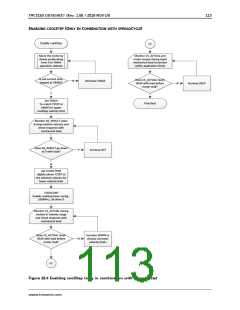
For UART based operation it is important to make sure that the CRC byte is correct. The following
example shows initialization for the driver with slave address 1 (NAI pin high). It programs the driver
to spreadCycle mode and programs the motion controller for a constant velocity move and then read
accesses the position and actual velocity registers:
UART write: 0x05 0x01 0xEC 0x00 0x01 0x00 0xC5 0xD3; // TOFF=5, HEND=1, HSTR=4,
// TBL=2, MRES=0, CHM=0
UART write: 0x05 0x01 0x90 0x00 0x01 0x14 0x05 0xD8; // IHOLD=5, IRUN=20, IHOLDDELAY=1
UART write: 0x05 0x01 0xA6 0x00 0x00 0x13 0x88 0xB4; // AMAX=5000
UART write: 0x05 0x01 0xA7 0x00 0x00 0x4E 0x20 0x85; // VMAX=20000
UART write: 0x05 0x01 0xA0 0x00 0x00 0x00 0x01 0xA3; // RAMPMODE=1 (positive velocity)
// Now motor should start rotating
UART write: 0x05 0x01 0x21 0x6B;
UART read 8 bytes;
// Query XACTUAL
UART write: 0x05 0x01 0x22 0x25;
UART read 8 bytes;
// Query VACTUAL
Hint
Tune the configuration parameters for your motor and application for optimum performance.
www.trinamic.com

 TRINAMIC [ TRINAMIC MOTION CONTROL GMBH & CO. KG. ]