TMC5130A DATASHEET (Rev. 1.14 / 2017-MAY-15)
43
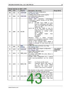
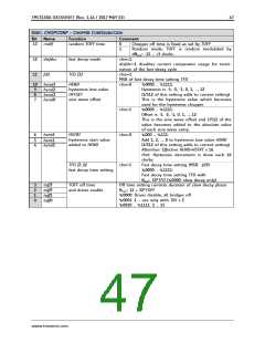
DRIVER REGISTER SET (0X6C…0X7F)
R/W
Addr
n
Register
Description / bit names
Range [Unit]
chopper and driver configuration
See separate table!
RW
0x6C
32 CHOPCONF
coolStep smart current control register
and stallGuard2 configuration
See separate table!
W
0x6D
25 COOLCONF
dcStep
(DC)
automatic
commutation
configuration register (enable via pin DCEN
or via VDCMIN):
bit 9… 0:
DC_TIME: Upper PWM on time
limit for commutation (DC_TIME *
1/fCLK). Set slightly above effective
blank time TBL.
bit 23… 16: DC_SG: Max. PWM on time for
step loss detection using dcStep
stallGuard2 in dcStep mode.
(DC_SG * 16/fCLK)
W
0x6E
24 DCCTRL
Set
slightly
higher
than
DC_TIME/16
0=disable
Attention: Using
a
higher microstep
resolution or interpolated operation, dcStep
delivers a better stallGuard signal.
DC_SG is also available above VHIGH if
vhighfs is activated. For best result also set
vhighchm.
DRV_
32
stallGuard2 value and driver error flags
See separate table!
Voltage PWM mode chopper configuration
See separate table!
R
0x6F
0x70
STATUS
reset default=
0x00050480
0…255
W
22 PWMCONF
Actual PWM amplitude scaler
(255=max. Voltage)
R
0x71
8
PWM_SCALE
In voltage mode PWM, this value allows to
detect a motor stall.
Encoder mode configuration for a special
mode (enc_commutation), not for normal
use.
Bit 0:
Bit 1:
inv: Invert encoder inputs
maxspeed: Ignore Step input. If
set, the hold current IHOLD
determines the motor current,
unless a step source is activated.
W
0x72
2
ENCM_CTRL
The direction in this mode is determined by
the shaft bit in GCONF or by the inv bit.
Number of input steps skipped due to higher
load in dcStep operation, if step input does
not stop when DC_OUT is low. This counter
wraps around after 2^20 steps. Counts up or
down depending on direction. Only with
SDMODE=1.
R
0x73
20 LOST_STEPS
www.trinamic.com

 TRINAMIC [ TRINAMIC MOTION CONTROL GMBH & CO. KG. ]