TMC5130A DATASHEET (Rev. 1.14 / 2017-MAY-15)
113
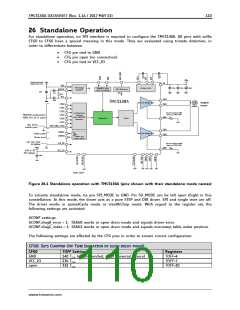
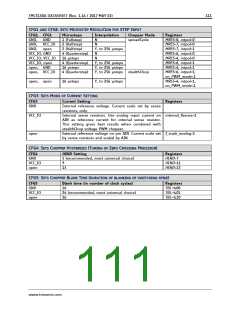
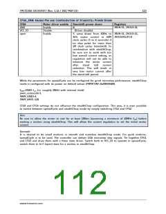
27 External Reset
The chip is loaded with default values during power on via its internal power-on reset. In order to
reset the chip to power on defaults, any of the supply voltages monitored by internal reset circuitry
(VSA, +5VOUT or VCC_IO) must be cycled. VCC is not monitored. Therefore VCC must not be switched
off during operation of the chip. As +5VOUT is the output of the internal voltage regulator, it cannot
be cycled via an external source except by cycling VSA. It is easiest and safest to cycle VCC_IO in order
to completely reset the chip. Also, current consumed from VCC_IO is low and therefore it has simple
driving requirements. Due to the input protection diodes not allowing the digital inputs to rise above
VCC_IO level, all inputs must be driven low during this reset operation. When this is not possible, an
input protection resistor may be used to limit current flowing into the related inputs.
In case, VCC becomes supplied by an external source, make sure that VCC is at a stable value above
the lower operation limit once the reset ends. This normally is satisfied when generating a 3.3V
VCC_IO from the +5V supply supplying the VCC pin, because it will then come up with a certain delay.
28 Clock Oscillator and Input
The clock is the timing reference for all functions: the chopper, the velocity, the acceleration control,
etc. Many parameters are scaled with the clock frequency, thus a precise reference allows a more
deterministic result. The on-chip clock oscillator provides timing in case no external clock is easily
available.
28.1 Using the Internal Clock
Directly tie the CLK input to GND near to the IC if the internal clock oscillator is to be used. The
internal clock can be calibrated by driving the ramp generator at a certain velocity setting. Reading
out position values via the interface and comparing the resulting velocity to the remote masters’ clock
gives a time reference. A similar procedure also is described in 19.5. For a STEP/DIR application, read
out TSTEP at a defined external step frequency. Scale acceleration and velocity settings, TOFF and
PWM_FREQ as a result. Temperature dependency and ageing of the internal clock is comparatively low.
IMPLEMENTING FREQUENCY DEPENDENT SCALING
Frequency dependent scaling allows using the internal clock for a motion control application. The
time reference of the external microcontroller is used to calculate a scaler for all velocity settings. The
following steps are required:
1. You may leave the motor driver disabled during the calibration.
2. Start motor in velocity mode, with VMAX=10000 and AMAX=60000 (for quick acceleration). The
acceleration phase is ended after a few ms.
3. Read out XACTUAL twice, at time point t1 and time point t2, e.g. 100ms later (dt=0.1s). The time
difference between both read accesses shall be exactly timed by the external microcontroller.
4. Stop the motion ramp by setting VMAX=0.
5. The number of steps done in between of t1 and t2 now can be used to calculate the factor
푉ꢐꢎꢢ ∗ 푑ꢉ
ꢃꢄꢄꢄ
푓 =
=
ꢢꢎ퐶ꢖ푈ꢎꢑꢝꢉꢀꢞ − ꢢꢎ퐶ꢖ푈ꢎꢑꢝꢉꢃꢞ
ꢢꢎ퐶ꢖ푈ꢎꢑꢝꢉꢀꢞ − ꢢꢎ퐶ꢖ푈ꢎꢑꢝꢉꢃꢞ
6. Now multiply each velocity value with this factor f, to normalize the velocity to steps per second.
At a nominal value of the internal clock frequency, 780 steps will be done in 100ms.
Hint
In case well defined velocity settings and precise motor chopper operation are desired, it is supposed
to work with an external clock source.
www.trinamic.com

 TRINAMIC [ TRINAMIC MOTION CONTROL GMBH & CO. KG. ]